My i-Telex Project 2015

In Germany, Italy, and in almost all of the other European countries the public Telex network no longer exists and since the shutdown of the last German telex exchange on 31.12.2007 it is no longer possible to get a "real" telex connection installed at home. So, some clever minds have produced the i-Telex System concept, a hobby Telex network that is popular with members and also telecommunications museums increasingly popular to use and to possess for demonstration teleprinters, because it's something different, with another person on the other end of the world to write "live" instead of allowing only a punch tape to run locally on the machine.
Using i-Telex You can use teleprinters faithfully and establish connections to other participants locally and around the world, provided they also have i-Telex. Members are happy to help with information on specific questions relating to i-Telex.
i-Telex is a hobby telex network via ordinary telephone lines or the Internet. Launched in 2000 by Philipp Hachtmann and Henning Treumann to awaken old teleprinters back to life. Philipp developed an adapter and a connection protocol, a teleprinter with TW39-Anschaltgerät (FSG) can be connected to a direct-equipped remote station via the telephone network with the appropriate over V.21 modems. As far as possible a real telex connection is been simulated. This was about 10 years the Telex Phone version 1. However, as appropriate modems for the system were increasingly difficult to obtain and also some additional functions, such as Keyboard dialing were required, it was decided to develop a completely redesigned version 2 and to allow connections over the Internet.
Here came Fred Sonnenrein on board and there was a new version 2, developed based on ATMEL microcontrollers. Version 1 is no longer available, but still compatible with version. 2 The Telex Phone Version 2 allows the user to operate one or more teleprinters so that they can be connected with each other and with other users of the Telex Phone internally, via the public telephone network or the Internet. As far as possible, under the real operation, the now unfortunately largely disconnected, telex network is simulated.
You may access the Telex Phone by either a regular phone number or an i-Telex number, which you can choose. It should be noted that with a VoIP connection of the analog mode (modem connection) does not work smoothly, so here is the i-Telex (Internet connection) to choose from. i-Telex is modularly structured, so it can be adapted to individual needs. If more than one device is connected, internal connections are possible by dialing internal extension numbers (00 - 99). There is thus a kind of simulated Telex private branch exchange. It can be selected directly from the keyboard of the telegraph or with a number switch (dial).
Just take care to use the correct router like Fritz!Box or similar with port forwarding. The Speedport Modell 723/724 A/B doesn't work properly..
If the installation has an i-Telex board, and the user has put a static IP or DynDns service then the teleprinter(s) can be accessed directly from an internet browser, or knowing the teleprinter's IP address of course. You may just try mine:
The i-Telex board has another feature, it can receive e-mails on the telex provided that the message is written in plain text, this option can be set on your e-mail software like Microsoft Outlook and others. To send a mail just follow the procedure her below:
[1] Check with the addressee what email address should be used for this.
[2] Open a new message and choose the option "plain text"
[3] You MUST compile the subject with +TX+ in the text otherwise the message may be ignored by the system.
[4] Write the message as you would do with a normal e-mail, but don't use "fancy" characters because the teleprinter cannot print them.
[5] Send the message and after a little while, depending on the settings of i-Telex, the email will be printed.
Here is an example of how to write to my personal Telex, which will be printed on an RFT F2000 teleprinter
mailto: This email address is being protected from spambots. You need JavaScript enabled to view it.
Subject: +TX+ This is a test email to see if all works as planned.
Text: Hi Franco, I am testing just the e-mail function of i-Telex, let me know if it works :)
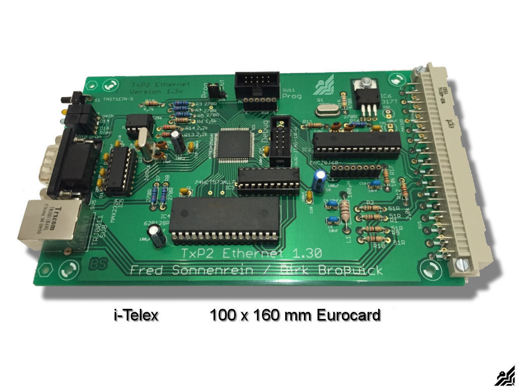
Telex Phone 2 is modularly structured. There are (100x160 mm) boards used in Europe's usual format so called Eurocards or Euroboards Since the space on these boards is often not exploited totally, functional units are partially (called "modules") combined or accommodated twice on a board. The connection of the boards is done with each other through a bus system. The bus consists of a power supply bus with voltages + 12V / + 5V for electronics and + 60V / + 30V for teleprinter and other connected devices.
The communication between the modules is via a "two-wire bus" (compatible with the I2C bus), there will be no "switching unit" needed, yet on the bus, about 10 connections can exist simultaneously. Technically, the bus is designed as a back-plane, alternatively, the boards can also be connected directly to each other also in a "modular system". How exactly do you accommodate the boards is up to you. From accommodations in wooden cabinets, and 19-inch racks to adventurous Tupperware trays, anything is possible. It's all up to you.
The i-Telex Hardware
The following boards are currently available:
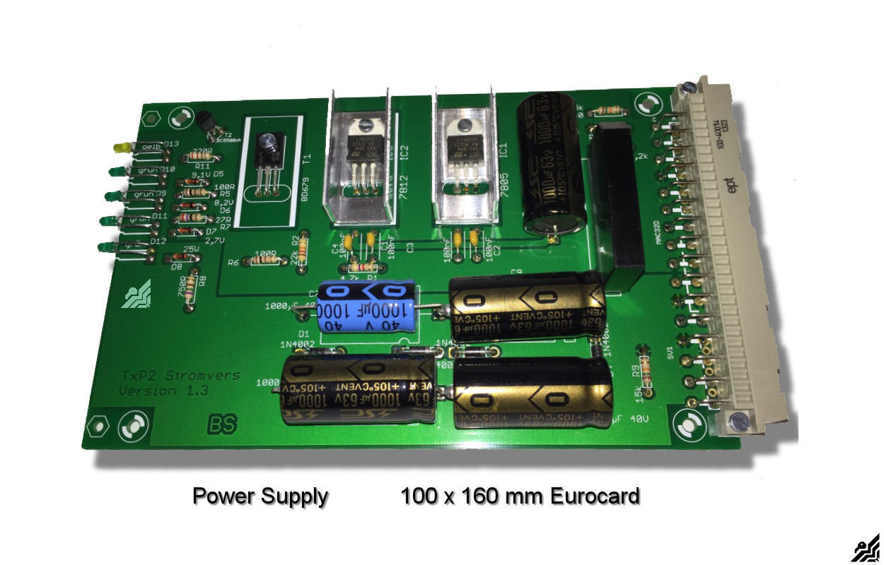
Power Board: provides the system with all the necessary voltages
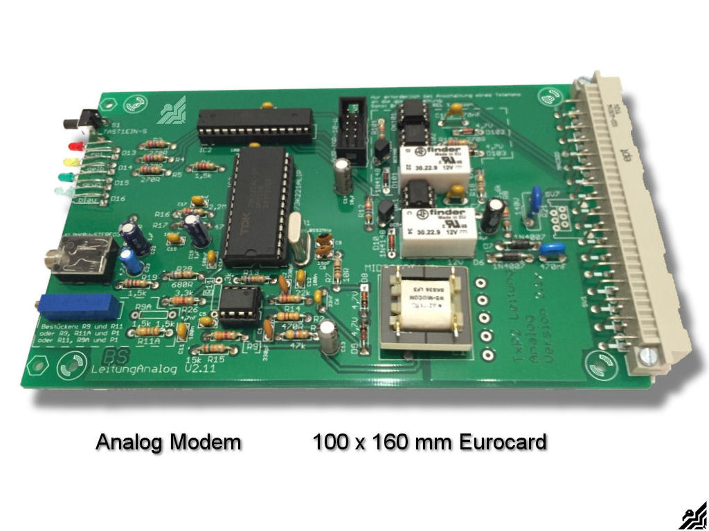
Analog Board: establishes the connections over analog telephone lines
Ethernet Board: establishes the connections over the Internet
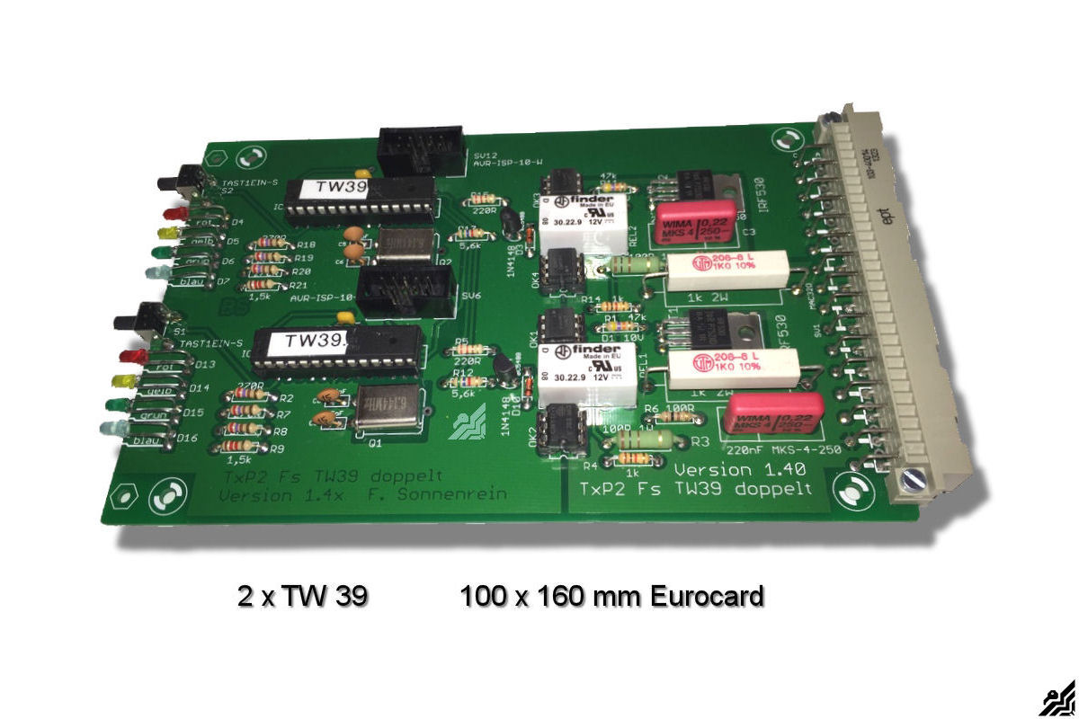
TW39 Board: for connection of telex standard TW39 protocol
ED1000 Board: for connection of telex ED1000-Standard
Also possible:
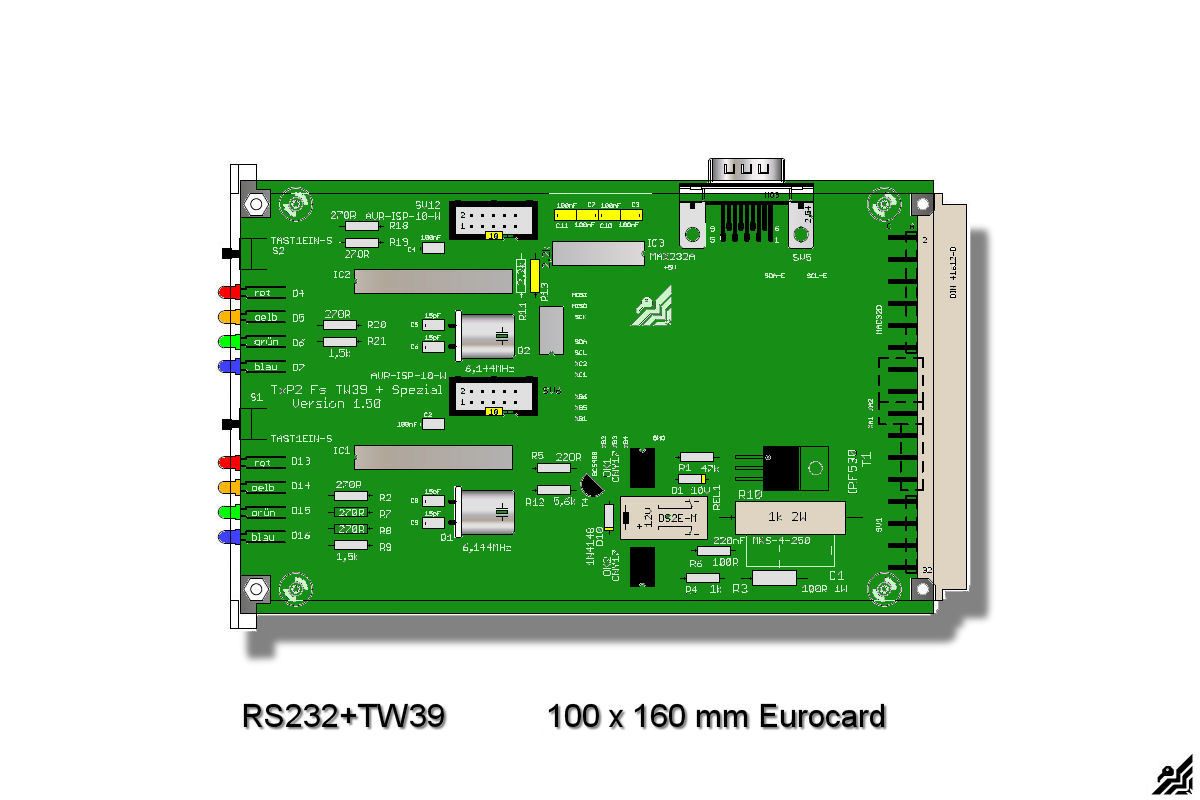
TW39 / serial Board: to connect a PC as a teletype - Connection board for Telegraph double current -
Image Puncher ,voicemail and diagnostic Unit
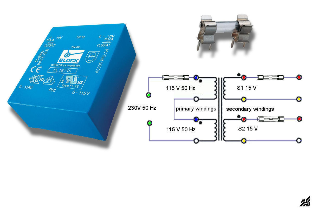
Keep in mind that you need also a transformer with two separate windings: 2 x 12V ( or max. 15V) with at least 10 VA each to supply the necessary voltages for the Power board and the other boards.
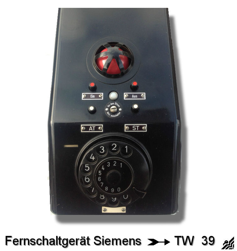
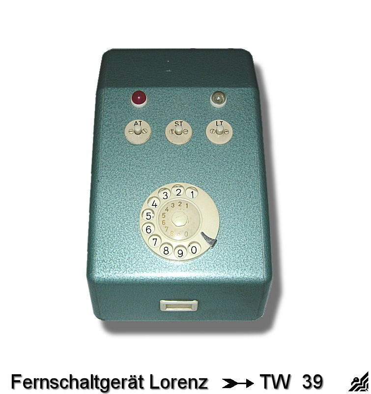
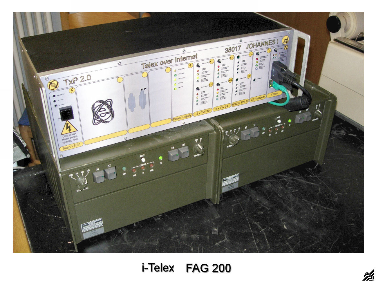
And you (must have)* a so-called "fernschaltgerät" (FSG), e piece of old-fashioned switch box with the TW39 protocol, you may find some still on ebay.de here above some examples.
* there is a new board available for telex equipment that doesn't have any "fernschaltgerät" (FSG) Remote Switch Unit. Just ask Henning for the details.
Where to buy the TxP 2.0 - i-Telex Hardware
As a source here is Henning Treumann to mention, one of the initiators of the Telex Phone project. He can send you the boards either as components for DIY purposes or as fully assembled boards at a cost to you.
The price of the most popular boards is as follows: ( as on 12/06/2015)
Power Board: 50 €
Analog Board: 50 € (the one that connects to the Phone line)
Ethernet Board: 65 € (the one that connects to the internet)
TW39 Board: 50 €
TW Board for teleprinters without an FSG 50 € without a Remote Switch Unit
ED1000 Board: 50 €
TW39 / serial Board: 50 €
There are a further € 5.99 shipping costs for Germany only.
( For other countries please contact Henning Treumann )
Please note that even when completely assembled PCB's are used, basic knowledge of the electrical and the soft soldering is necessary because you need to configure your personal Telex Phone by yourself at home. But this really is limited to a minimum and should for people who ever had a soldering iron in his hand, be done without problems in a few minutes :).
The whole project is well documented and the appropriate documents in PDF format can be found on the website here:
My Telex Phone < > i-Telex Project 2015
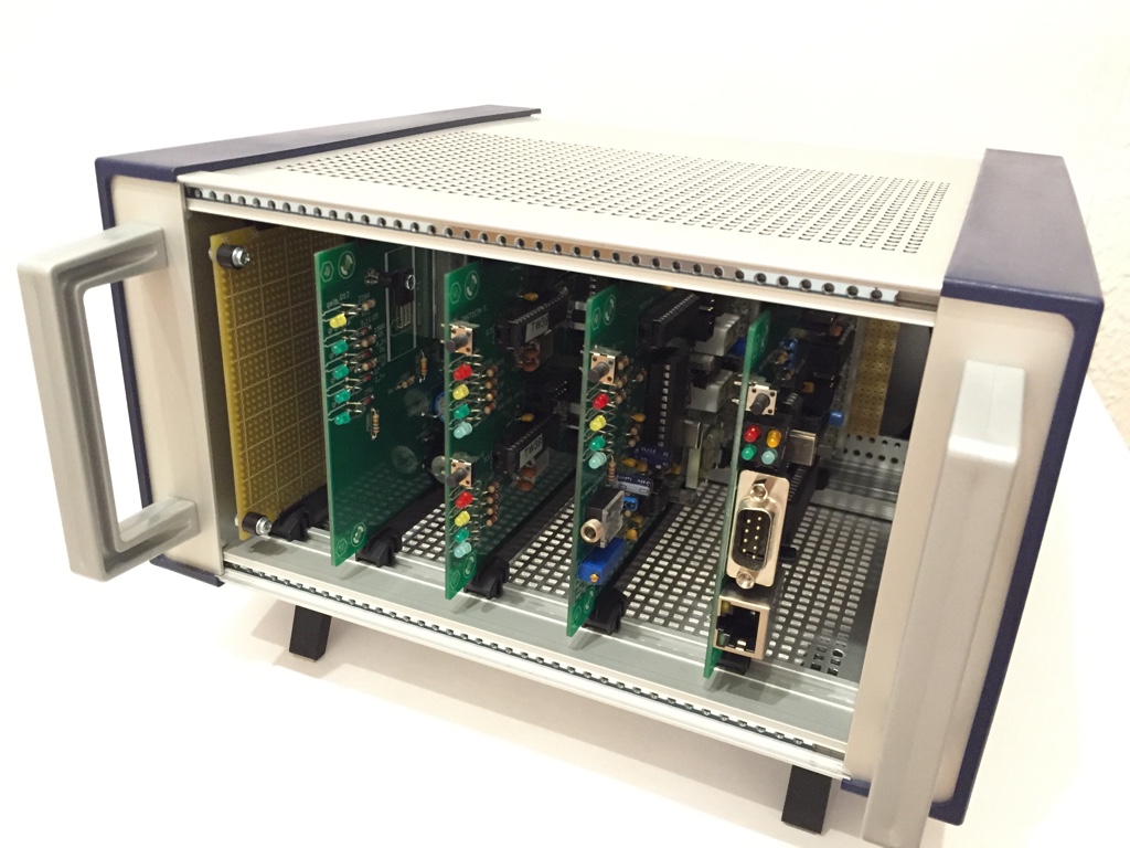
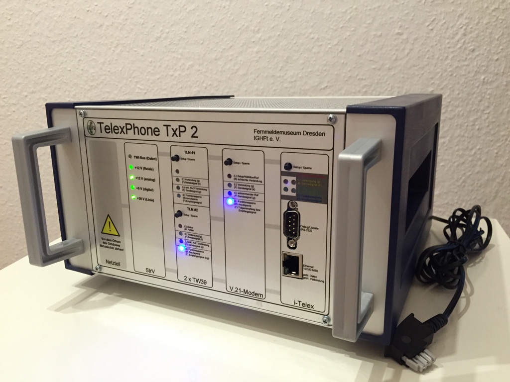
I was inspired by the project realized by the Fernmelde Museum Dresden , (Thomas) because it has a stunning professional look.
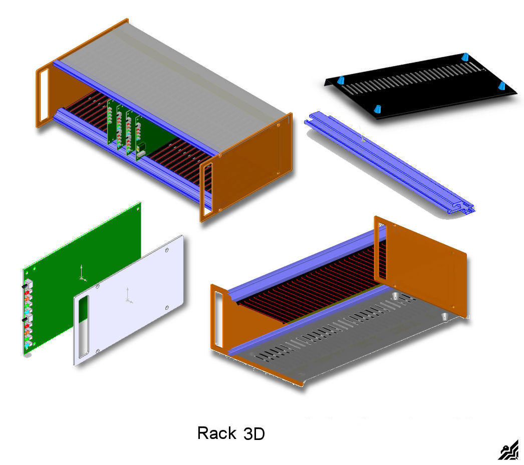
I decided to recover a 19" Eurocard rack pieces from some old unused CNC equipment to make something similar to this one but I will come back later on this issue. To put together all the "mechanical parts" without surprises, I designed the boards and rack assembly on Solidworks 3D Cad program. If any mistake was made in the dimensions, etc. in Solidworks you see it before taking pieces effectively in your hand. Only at the finished drawing, I started to cut the Aluminium parts, ribs, and other pieces of the rack structure.
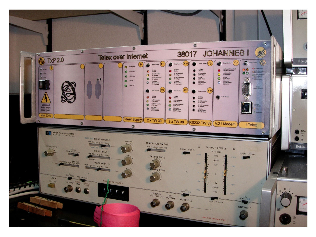
For my own configuration of the TxP 2.0 i-Telex I've bought the following from Henning:
1x Power Board: (Strv)
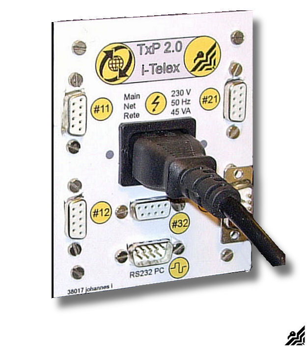
1x Analog Board: (Modem V.21 - Phone line - Audio jack)
1x Ethernet Board: (Telex over IP - RS232 Debug / Update)
2x TW39 Boards: (to connect four different telex equipment at once)
1x TW39 / serial Board: (To use a PC as a Telex + 1 telex equipment output)
This board was not available at that moment but will arrive.....
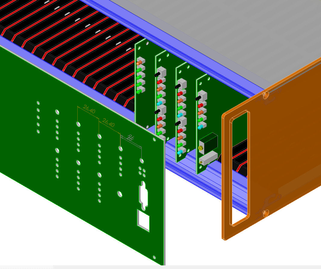
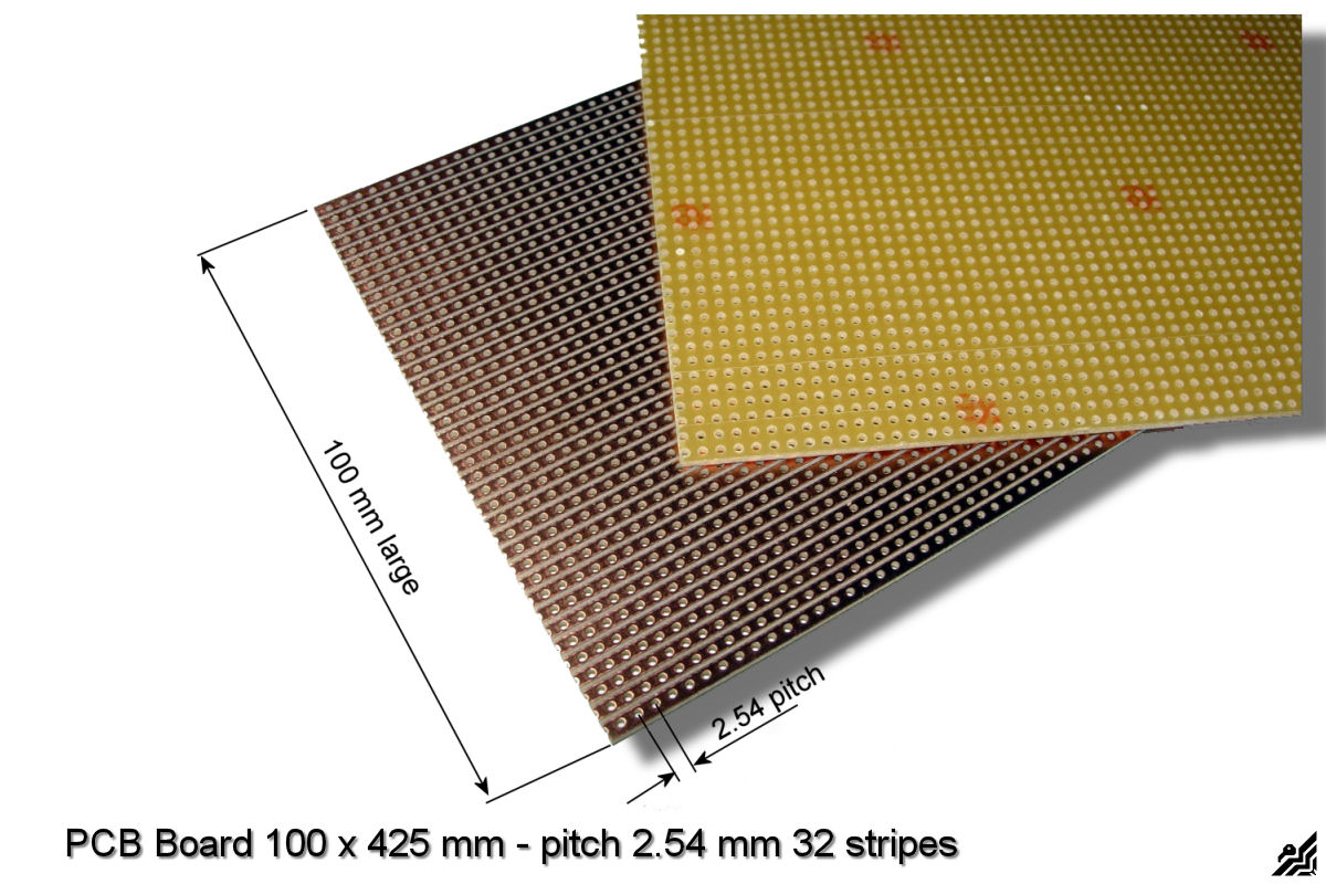
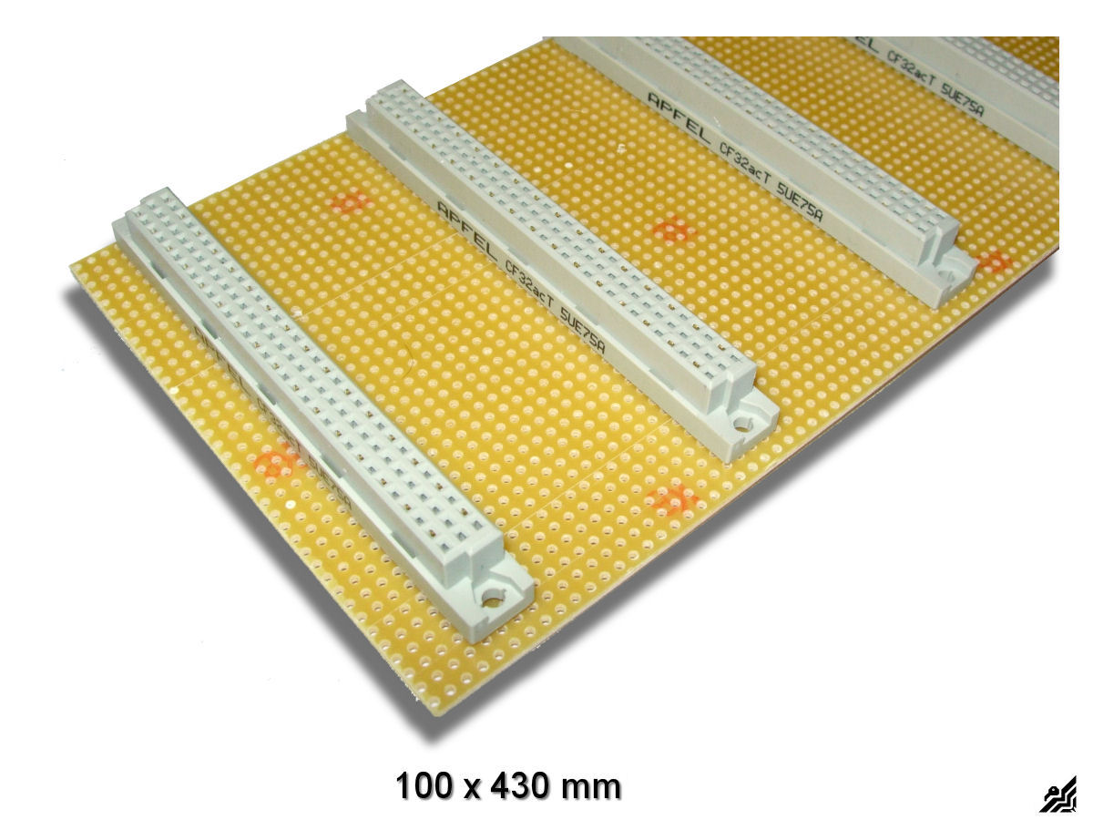
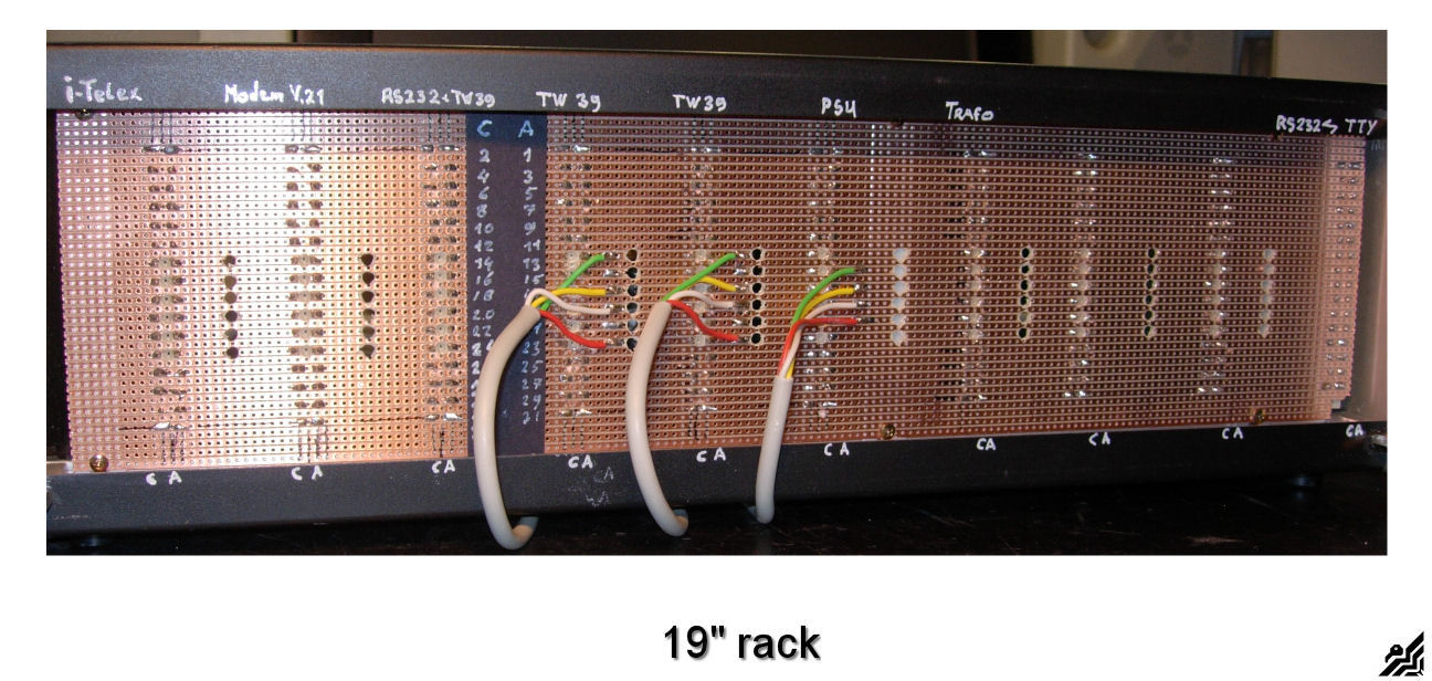
As the system itself uses an I2C Bus to communicate to the various boards, this bus can be fed through a suitable back-plane pcb and in the same time the back-plane is the mounting structure for your sockets, easy to install and to operate. I used a back-plane with 2.54 mm pitch (height 100 mm and length whatever your project requires) with 32 stripes.
A transformer (normal or PCB type) with two separate secondary coils 2 x 12V or max. 15V at least 10 VA each. Primary tension according to your country.
In my case, I made a separate Eurocard for the pcb-transformer and some secondary components like fuse holders LED and rectifier bridge for other applications I want to install in the future. I also put a power switch at the front to cut off power easily from the front side of the rack. It is a push-button toggle switch with double contacts.
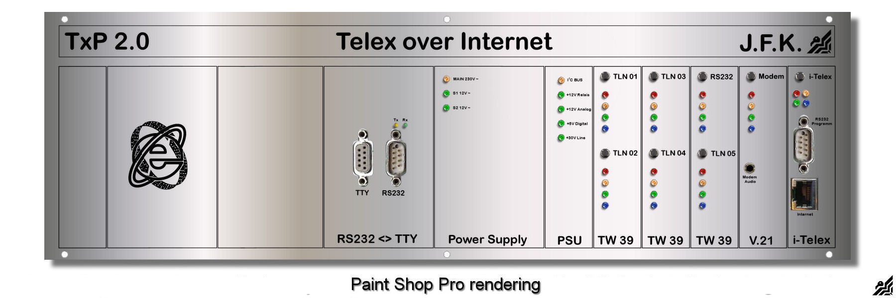
Ok, now it was time to get the rack done, some 3D drawings and verifying and then made a rendering to see if I had done things the right way.
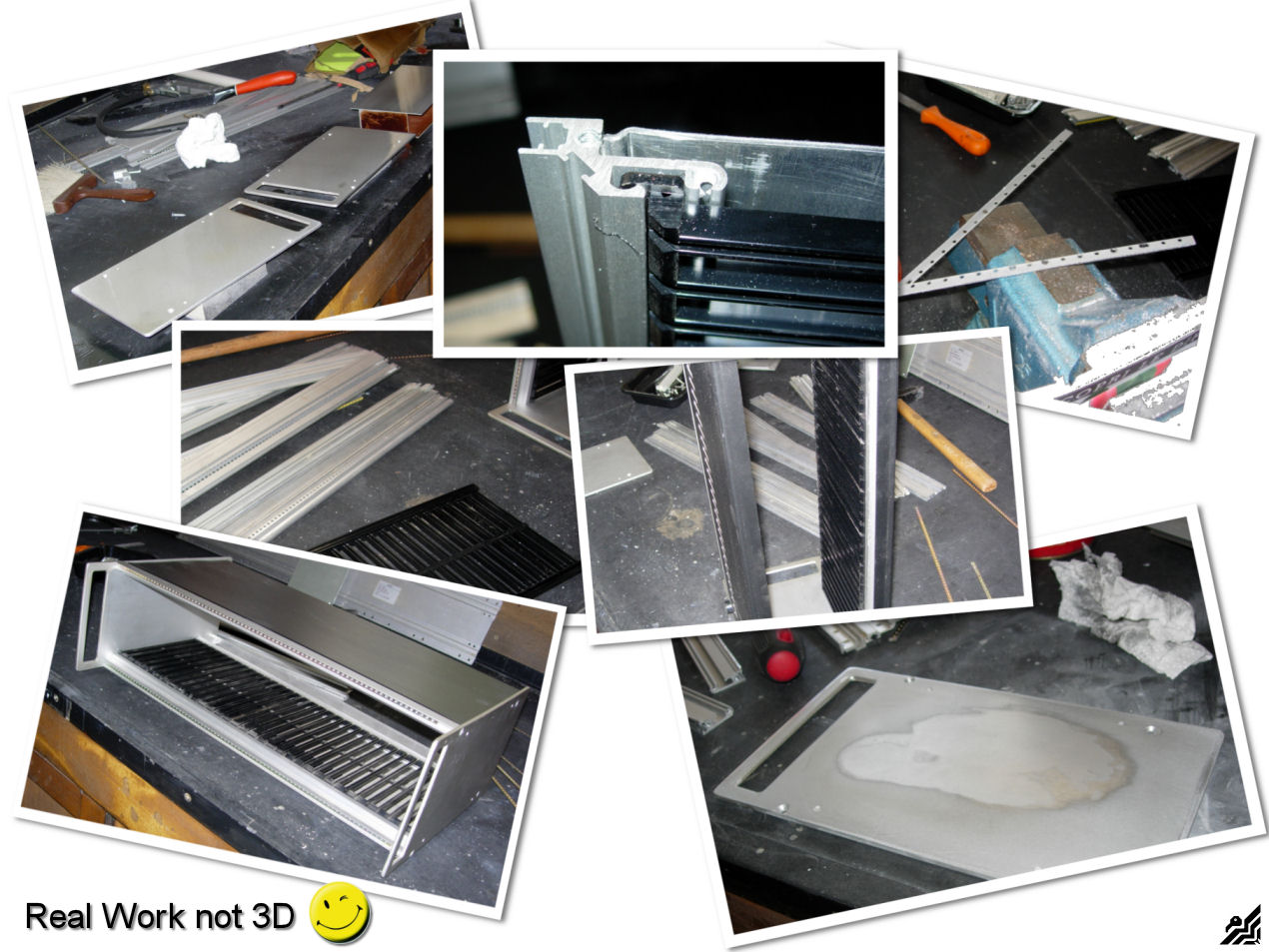
The result seemed to be ok so I went to the garage to do the "real" work, cutting and drilling the Alu pieces of the rack. Fortunately, I had a bunch of material left from some other unused CNC equipment such as side panels, ribs, and extruded Alu profiles that would do just right for my purpose. Not all the pieces could be used as they were so some modifications took place to get what I really needed.
As next I put together everything to obtain my finished rack. I put in some of the boards there are already here to see if the fit as I planned. The result was ok so I went on with the next step, the front cover or front plate as you wish. At first I took a look at the layout from Thomas (Fernmelde Museum Dresden) because I liked very much the professional touch of it.
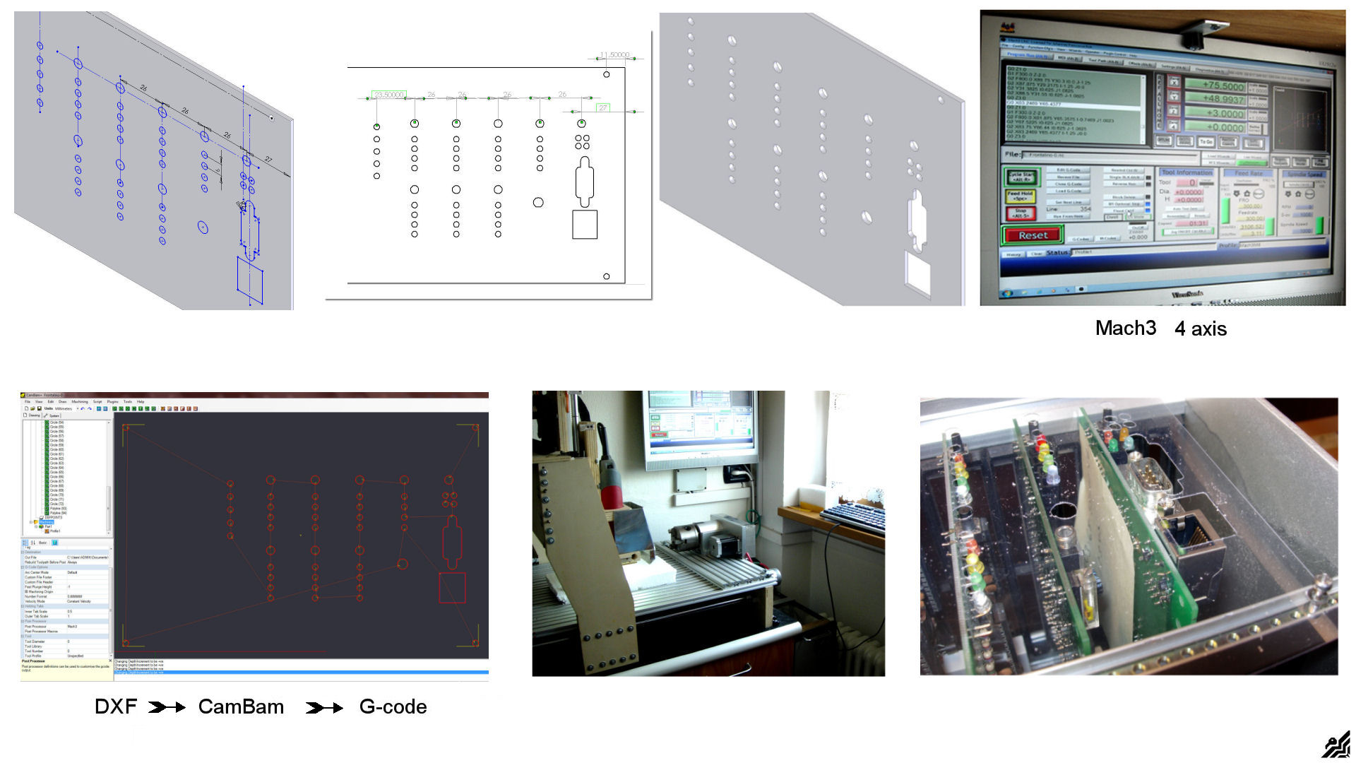
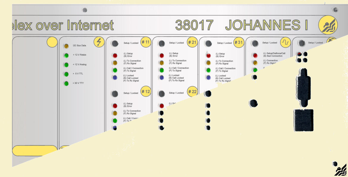
I have an old graphic program on my PC from Jasc.Software , it's called Paint Shop Pro V.9, it was designed for photo retouching but I used it to create the front of the rack. It has the possibility to configure the work-space into mm or cm so for the scope I took the measures of the front plate 130 x 432 mm and created a blank. Then divided all into single rack slots to space the single boards as they would be in the real rack. This was one of the first results I obtained.
Now the look of the front plate was defined, i put the real boards in place and take some measures to create the drawing for the holes and slots to be cut out of the aluminium. I drew this on Solidworks and made some rendering. As I had only one piece of anodized aluminium I couldn't risk to make any mistakes in the drilling and milling so I used an acrylic transparent sheet of 0.8 mm thickness to print on the layout. Then put the printed layout (transparent) on the front of the rack. As I could see through everything, it was quite simple to establish witch hole was right and witch hole needed to be corrected.
It was fitting almost perfectly so I made some minor corrections and took a cardboard with the exact size of the aluminium and cut out this out also. I used this cardboard template to print the layout on, just to check if the HP Printer would keep the exact dimensions and did not distort the image of the final layout.
It was fitting perfectly so I saved the final image to use after making the aluminium front plate in a later moment. In the mean time I went on with the electronics, as all the boards come with a suitable socket, I prepared the back-plane pcb for soft soldering the sockets. The sockets are female with pins that fit directly to the pcb without any drilling or other adjustments as they have a pitch 2.54 mm too.
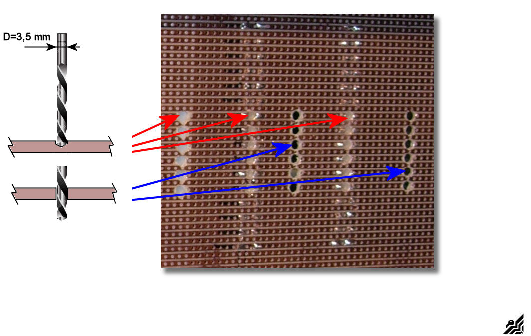
The single boards may have the connections on their sockets separated, that means every single contact that NOT belong to the bus system should be separated, to do so, you must remove the copper mechanically from the pcb back-plane.
To remove the copper I used a drill bit of 3.5 mm diameter and drilled trough the board or just half way where the sockets were, otherwise I drilled just trough all of the pcb. I was just taking care to remove the copper of each stripe. In the user manual there are instructions wich stripe / contact should be single and where are the stripes that carry the bus signals that can be leaved untouched.
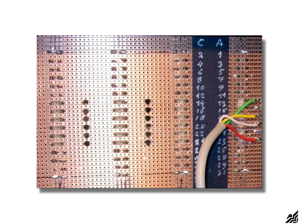
Here I have soft soldered the first cable on the double TW 39 board socket following the instructions from the i-Telex documentation. Then I continued to the others, like the transformer , power switch ecc.
I have installed some of the cables, the transformer and all the other boards now, and made an outlet socket on the back of the rack to collect all the connections to the outside in one single panel. I used the same procedure as for the front panel using a inkjet HP printer as described here below.
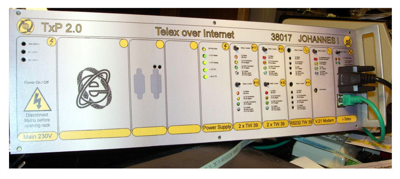
As everything is installed now and also tested, and working well, I dedicated some time to prepare the front-panel with the final layout. I used another procedure as the one Thomas was using, he laser-printed on a transparent sheet. As I don't have a laser printer but an A3 HP inkjet, I printed the layout directly on cardboard.
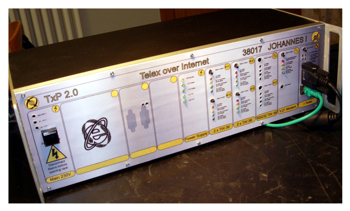
I glued the cardboard to the aluminum front panel using double adhesive tape (that was a failure as you can see later in the pictures because there are several visible flaws on the surface, I will make a new one later on )To protect the layout from scratches or other environmental "dangers" :) I covered it with a satin transparent adhesive sheet. Here below are the final results of the building of my TxP 2.0 i-Telex equipment.
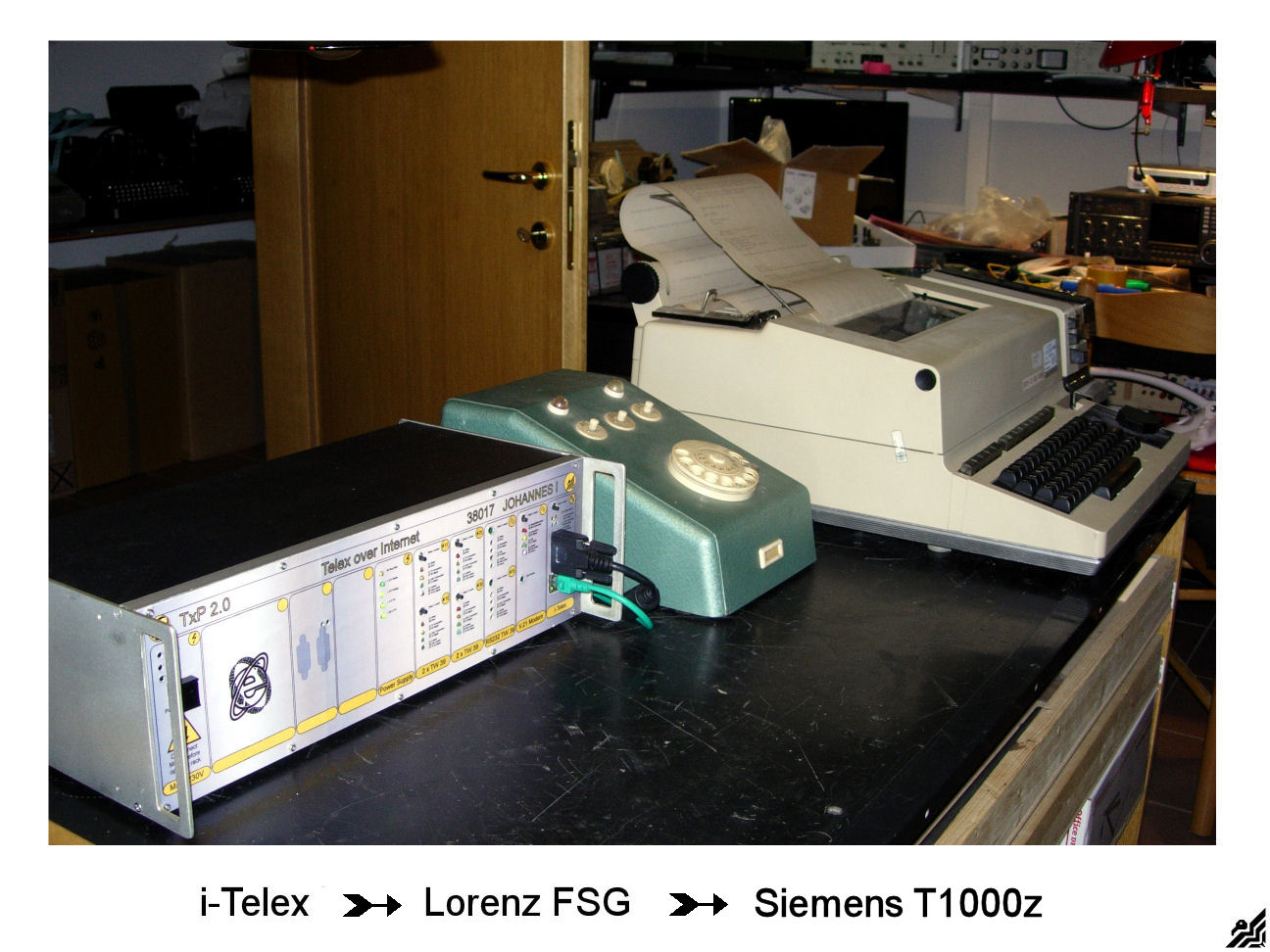 The making of this i-Telex TxP 2.0 Telex Phone equipment was really fun. As I have a small collection of teleprinters they stood always in an angle doing nothing else than collecting dust :), so now they are connected to the "rest of the world" in a real telex network and working fine as for 30 or more years ago, thanks to some fine clever minds as Henning , Philipp , Fred , Alex , Martin , Thomas , Richard and many others that want to keep TELEX alive!
If there is something that you want to know more how about I realized my project or other useful information for your own project just contact me, German Dutch Italian, and English speaking :) at:
This email address is being protected from spambots. You need JavaScript enabled to view it.
For buying hardware or other technical information about the board development or other or use this mail:
This email address is being protected from spambots. You need JavaScript enabled to view it.
Here is a list of i-Telex users around the world.
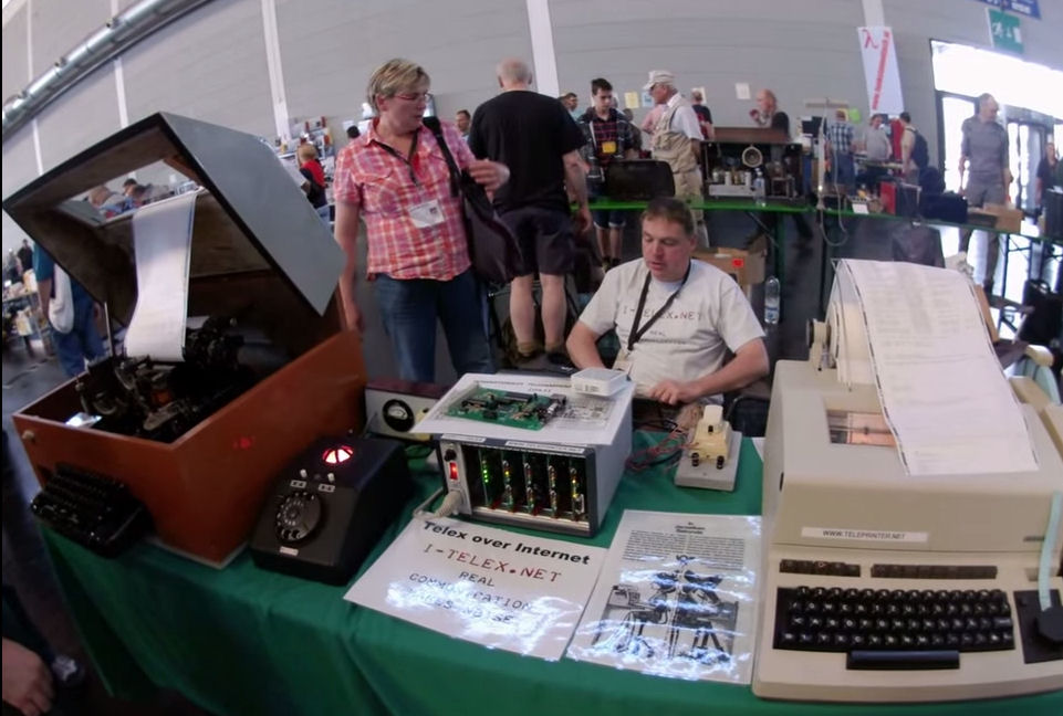
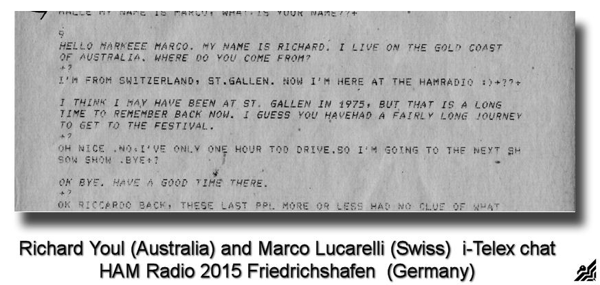
In Germany, Friedrichshafen on June 26-27-28 the HAM Fest HAM Radio 2015 has opened the doors, an international fair about radio amateurs and of course also the i-Telex was there:
Live chat on HAM Radio 2015
Installing my Telex equipment on i-Telex
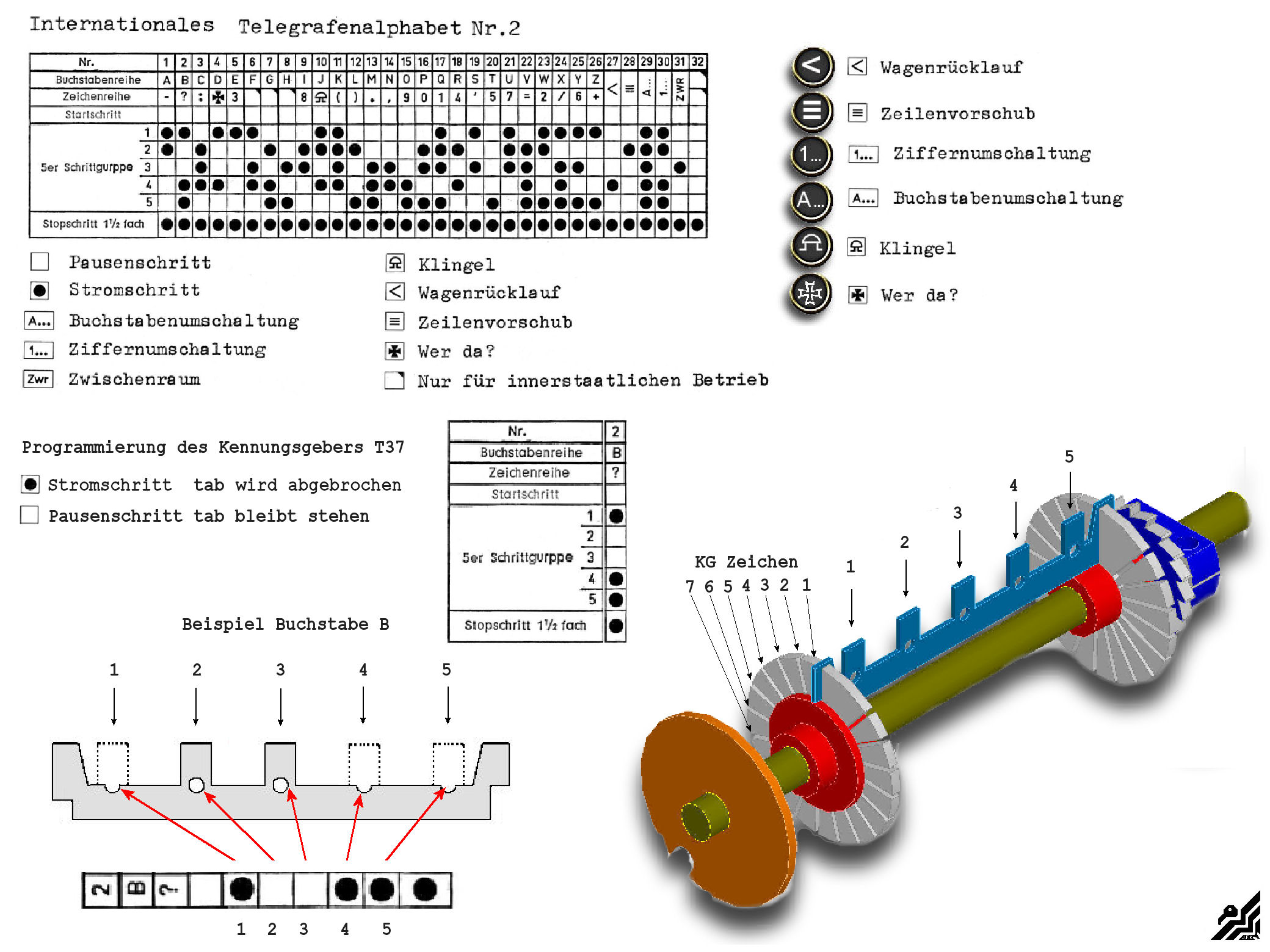
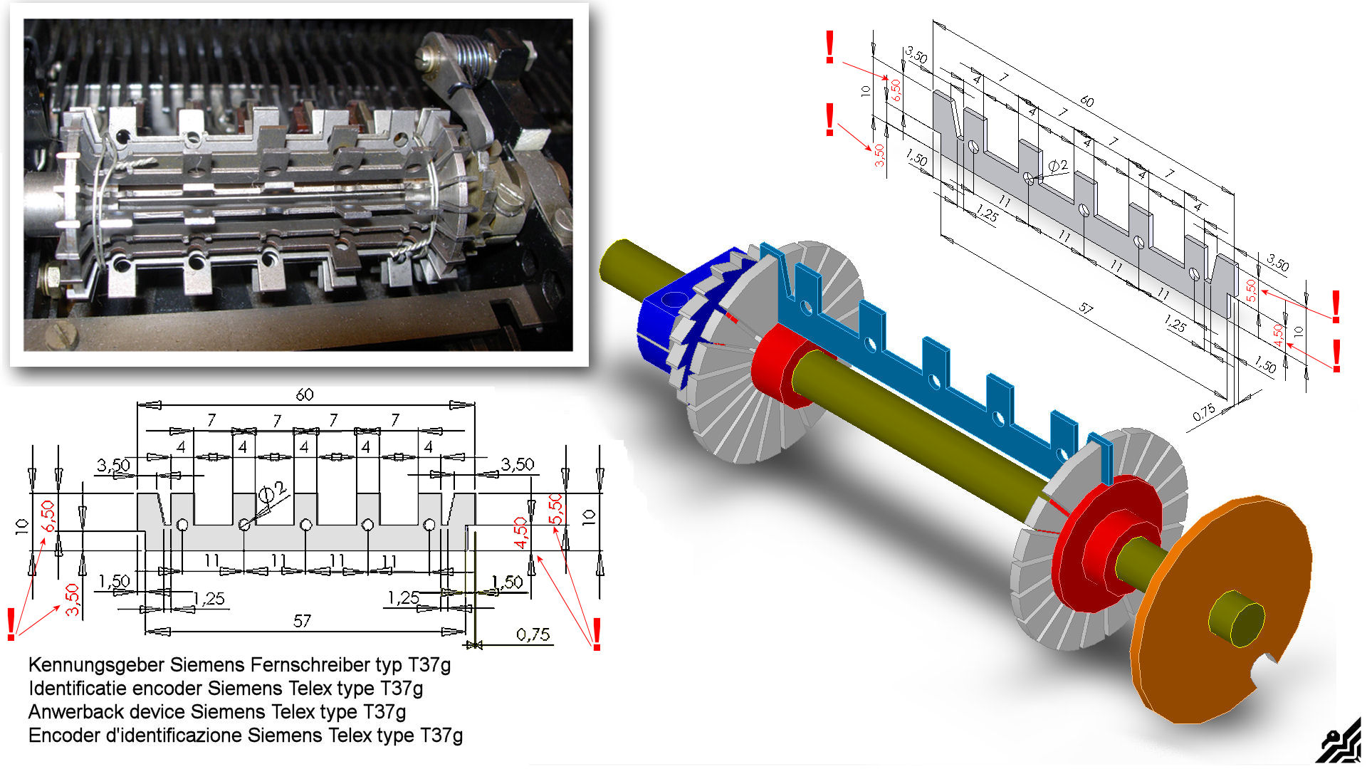
As I'm planning to use both my Siemens Telex T37g as secondary teleprinters, they should have an answer-back device, some kind of unique identification of the Telex itself. If the caller presses the "Who Is" button, the answer back device on the other side (My Telex) will send the Telex ID, so the caller can read it and be sure he is connected to the correct Telex or extension.
Usually, the i-Telex will use a number (the i-Telex number if possible) and the name (The i-Telex Member if possible) if any characters are left, the Member country. In other cases, members want to keep the "original" answer-back settings.
As an example, the ID of my answer-back device on the main Telex the Siemens T1000z1/z is as follows:
The i-Telex number 38017 then my name johannes and as last the country I for Italy 38017 johannes I
There are some characters used by the telex for special functions. The picture above shows you how to break out the tabs for the "Who Is" function described earlier.
The first T37g has a fully assembled answerback device. The second T37g Teleprinter had only the shaft, bearings, and sprocket, the ID Cams weren't provided, so I drew an example in 3D to make some on my own. I've put the drawing and the 3D rendering here below if someone wants to make their own cam too.
The dimensions are from my own Telex, be sure to check yours before start making them, as there could be some small differences.
This email address is being protected from spambots. You need JavaScript enabled to view it.
 To be continued as soon I stop running