")
")
")
")
i-Telex Firmware
This page contains backup information for the i-Telex Firmware written by Fred Sonnenrein as used in the ISP programming procedure.
There are four categories of Firmware. Alpha / Beta / Stab for the interface boards towards the teleprinters
Ethernet for the ethernet interface board.
Please consult the part below before attempting to use ISP Programming.
ISP Programming uses the Alpha, Beta, and Stab files.
You need a special flat cable for that purpose (see the manual)
To program the Ethernet board you need a PC with a serial port and a null-modem cable.
- Alpha Version contains the last working version of each Firmware.
- Beta Version contains the actual beta release of a Firmware to be tested.
- Stab Version contains the last stable working version of each Firmware.
- Ethernet contains a row of working releases with progressive numbering as a ZIP package.
Instructions for updating i-Telex boards with ISP
1 Preliminary remark
Almost nothing can go wrong! A little bit of skill is required... Only the Ethernet network board can reprogram other cards (with "simple" processors).
The Ethernet board itself must still be updated via the serial interface. The firmware is downloaded from the website during the update.
All stable standard versions (Stab) and Beta test versions are stored on the file server.
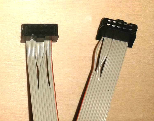
2 Programming cable
The most complex part is the making of a programming cable. This programming cable must have a 10-pin female post
1-1, 2-4, 3-7, 4-2, 5-5, 6-6, 7-3, 8-8, 9-9, 10-10
This sequence looks confusing but has the background that a connector is used on the Ethernet card, which actually has a different function.
The cable can easily be made with normal 10-pin ribbon cable (about 50 cm long) and 10-pin crimped post sockets by
3 Programming procedure
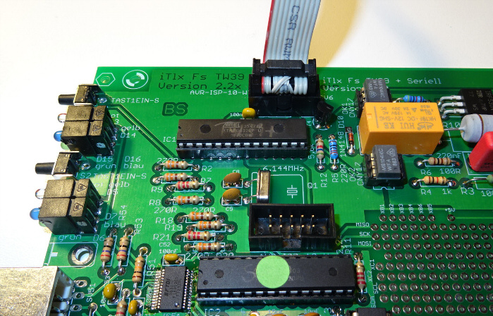
1. Plug one end of the programming cable into the "Debug" header of the Ethernet board
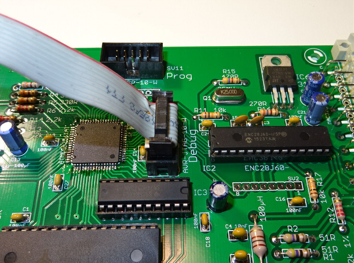
2. Insert the other end into the programming socket of the board to be programmed (target board)
3. The Ethernet board must be in operation and connected to the Internet.
4. open the following page in a browser: 192.168.111.222/isp.cgi. Replace 192.168.111.222 with the local IP address of the Ethernet board.
5. Enter the configuration password if necessary.
6. In the "Path to server for binaries" box, specify the address where the binary files are stored. do not put https:// in front!
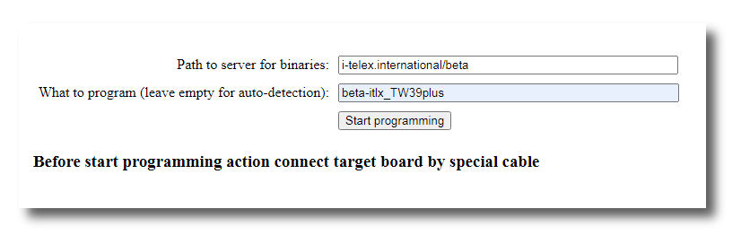
7. leave the field "What to program" empty (for special applications see below 13.)
8. now click the "Start programming" button During the programming procedure:
a. An identification of the existing software of the connected target board is read out.
b. A file of the same name with the extension .txt is downloaded from the "update server" and the correct hardware
c. A file with the same name and the extension .bin is downloaded from the "update server" and programmed on
10. if at an early stage, something is not working correctly, an error message appears, e.g.
a. "ISP program enable failed. Check connection to target board": Cable not connected correctly.
b. "No identification on connected target found. Select program manually": The chip on the target board is new or does not contain a valid identifier.
c. "Download xxx.txt socket open failed code -1": Probably a wrong path to the "update server" was specified.
d. "Download xxx.txt fileserver error code 404": Probably a wrong path to the "update server" was specified or a file matching the identification is not saved on the server.
11. if a message with the final sentence "Click here after all LED on i-Telex board went off again." the programming process was started, i.e. an identifier on the chip of the target board was detected and the relevant files are also available on the server. After all LEDs on the Ethernet card have gone off (between 30 seconds and 2 minutes) "Click here" should be clicked, and then the programming menu appears again, supplemented by the result of the last programming process:
a. "Success: XXX bytes written to flash, no failures: Programming successfully completed.
b. "Failed: XXX nominal size, YYY bytes written to flash, ZZZ failed: Unfortunately something went wrong. Try again.
c. "Signature mismatch: byte X is Y should be Z": The connected chip does not have the correct type.
12. for boards with two interfaces, both modules must be updated one after the other! For a further programming procedure, connect another target board or the other "half of the board" (may be done under voltage) and again "Start programming" (Step 8)
13. Programming new chips or repairing defective programming
When the message "No identification on connected target found. Select program manually" the software to be
Details are available here.
Instructions for updating the Ethernet board.
1 Preliminary remarks
Almost nothing can go wrong! What you need is a PC and a so-called Null-Modem cable.
The Ethernet network board must still be updated via the serial interface.
The firmware can be downloaded from this website on the Homepage Home > Ethernet tab.
here is the last stable working version stored.
You can download a complete package as .ZIP file. Just unpack the zip file in any directory you like
2 Programming cable
The null-modem cable should be plugged into the front RS232 socket on the Ethernet board,
the other end should be plugged into an available RS232 socket on the PC.
You must identify which Com Port you are using, eventually, you must / could edit the update.bat file
which is present in the unpacked zip file.
It would look like this:
fboot.exe /C2 /B38400 /Pmain.hex /Vmain.hex pause
where /C2 indicates which Com Port is used, to change from 2 to 1 just change the file to /C1
/B38400 indicates the Com Port Speed, standard speed will be overwritten at execution of the batch file.
3 Programming procedure
1. Be sure that the ethernet board is off. then launch the update.bat file.
2. As the procedure starts a screen like this should appear:
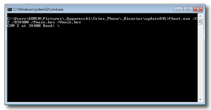
3 The program is running and is waiting for the serial connection to be initiated showing a rotating "slash":
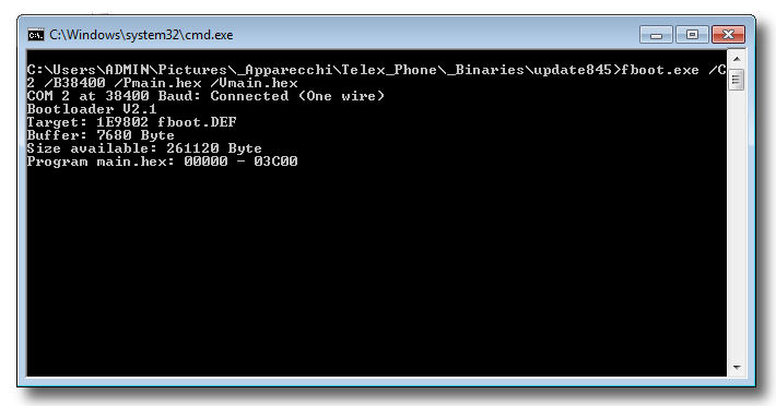
4. Now turn on the power on the ethernet board. The screen will change to somewhat like this, indicating the progress of programming.
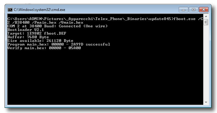
5. After writing the firmware to the ethernet board it will be verified to check on errors:
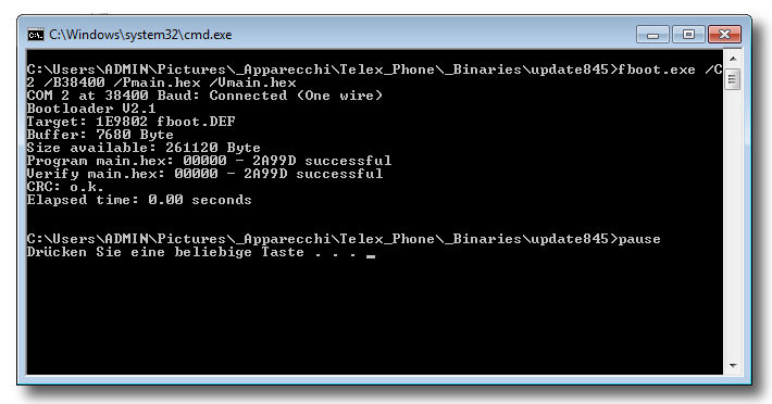
6. As the program ends there will be a screen like this where the results of the firmware update are displayed:
7. If there are any errors just try another time starting at point 1. If you get still some error messages: like CRC Error,
try to decrease the transfer speed, editing the update.bat file to /B9600 or even down to /B2400.
8. If the update was successful, you must reset the ethernet board to activate the new firmware.
Just turn off the power and re-power again after a few seconds.
11. To verify the Firmware and Settings just use your browser and login to the Ethernet board.
The actual firmware version will appear like this: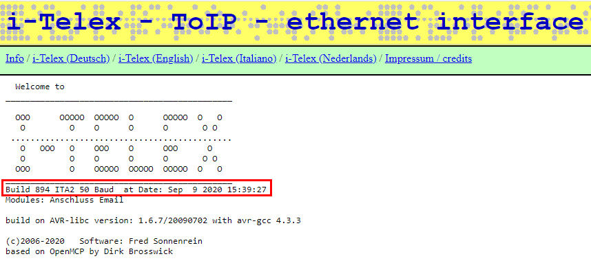
Binaries Table with path & name of the available file
AlphaPath: AlphaContent: alpha-itlx_ED1000 |
BetaPath: BetaContent: beta-itlx_ED1000 |
StabPath: StabContent: stab-itlx_ED1000 |
Ethernet Path: EthernetContent: Version 897 897.zip Version 875 875.zip Version 863 863.zip Version 845 845.zip |