")
")
")
")
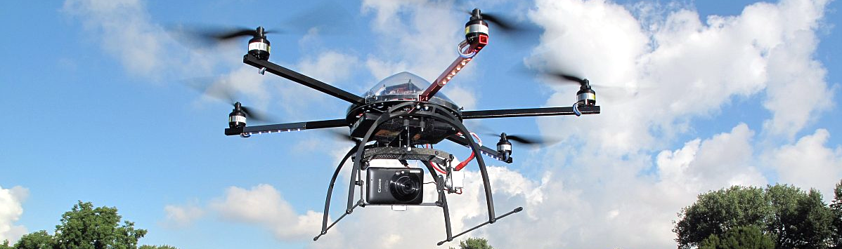
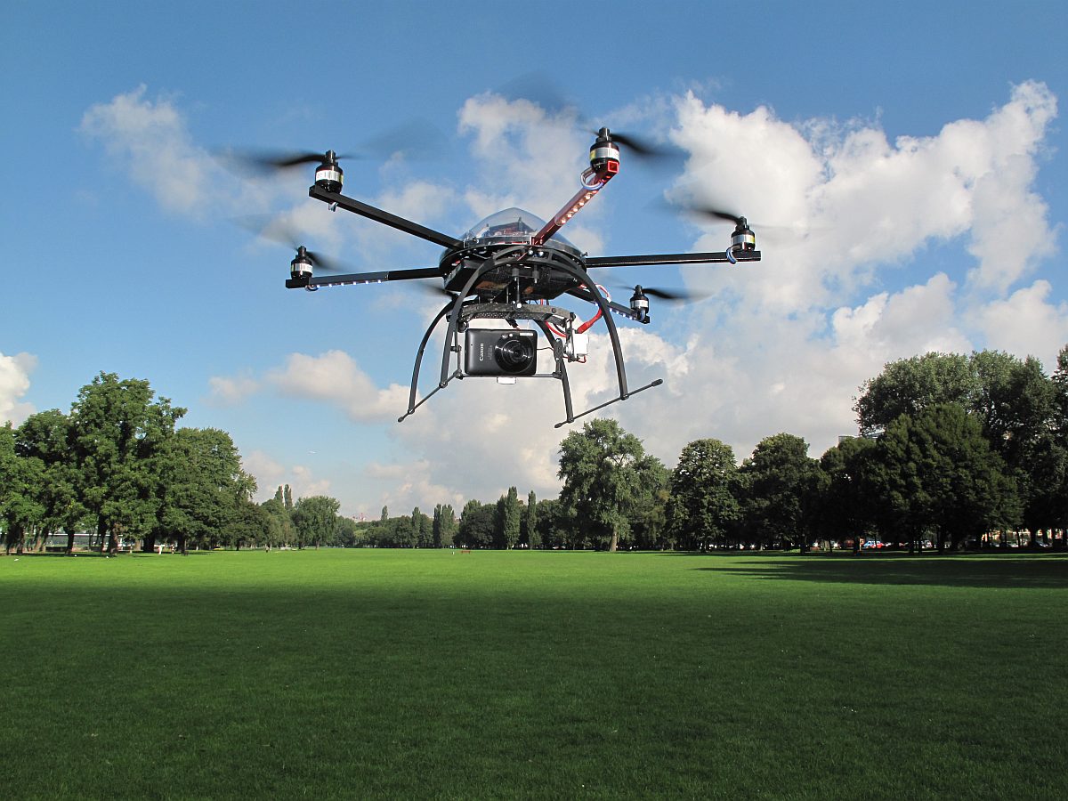
Mikrokopter -Hexakopter - Drone
In the beginning:
Nowadays, you can buy a drone almost everywhere, no assembly or so required, open the box, put the battery in, turn it on, fly, and start taking pictures or shooting a video. Things were different those days.
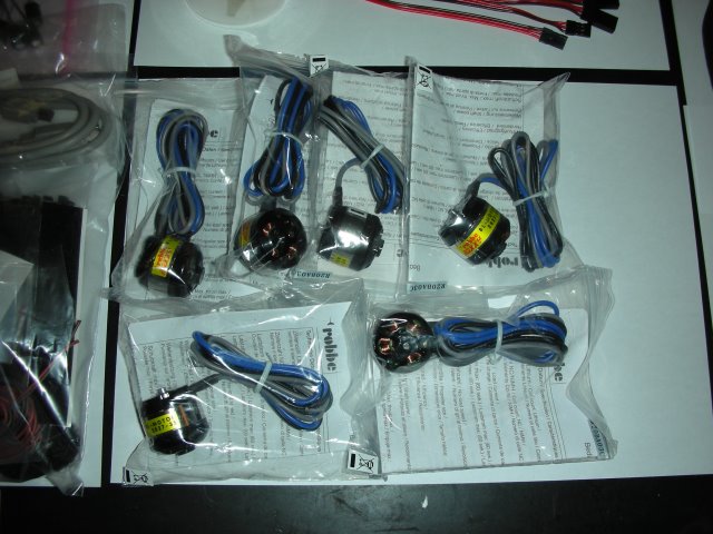
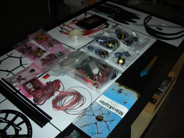
In the year 2008, I saw some nice German web pages about some amateurs who had developed a drone (Quad, Hexa, Octo) all with open-source firmware and nicely constructed hardware. There was also a forum (it sadly disappeared) where the whole "Mikrokopter Community" was exchanging their experiences, with hints and tips on how to improve the overall performance of your own drone. It was quite interesting and I decided to buy one of the earlier models, a so-called Hexakopter. yes written with a "K" because it is all German-based. The package comes as a kind of DIY project, all the parts are there but you had to build and mount it by yourself, an early kind of IKEA stuff. When you unbox everything it will look somewhat like this.
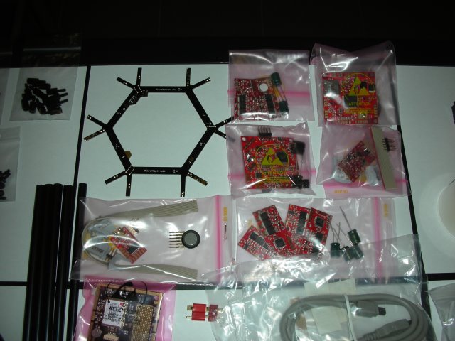
On the Mikrokopter.de website was a dedicated page on how to put it all together, it was a very extensive documentation and I did not experience any difficulty building the "standard" version of the Hexakopter. There are basically three different documents, the first about the electronics, PCB, and such stuff. The second type is the mechanical build, with all the tiny screws bushings nuts, etc. The third and most important part was the firmware, loading and customizing it to be used by a "Newbie" like me.
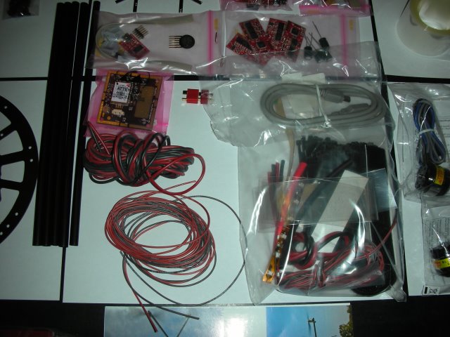
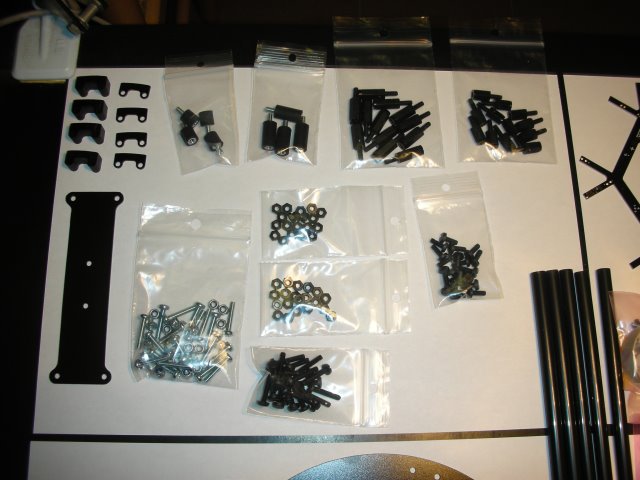
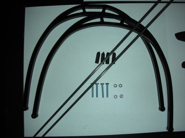
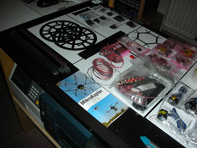
I went on to build the mechanical part at first because you need a solid base to put the electronics on later. Here are some pictures of the process.
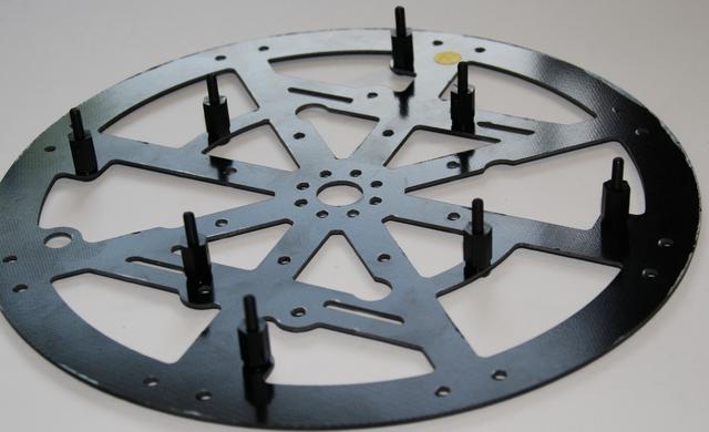
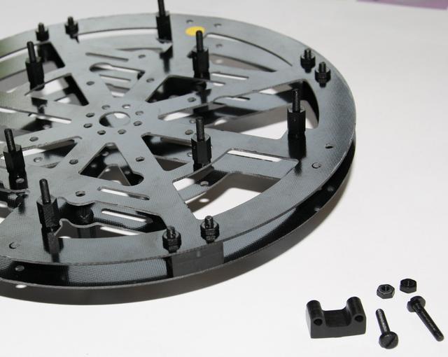
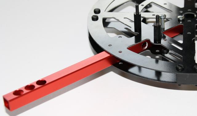
The red aluminum profile is the main beam as a motor mount, the red color, (just one of the beams) indicates the front of the drone. The other 5 are black and have been installed after.
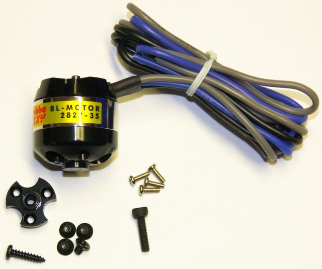
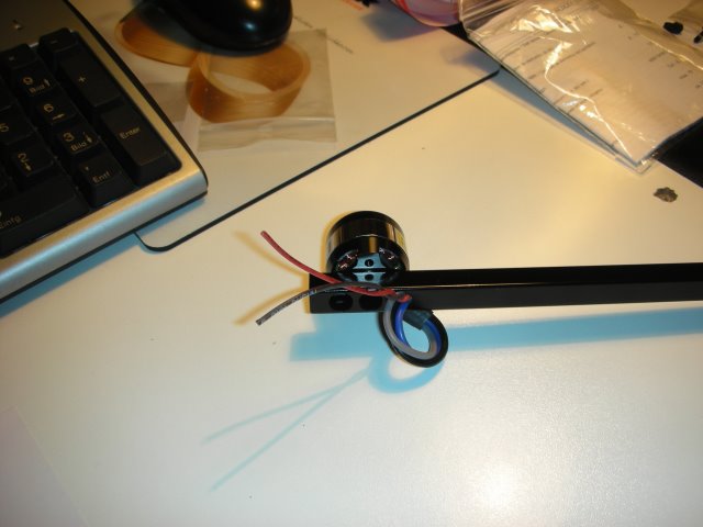
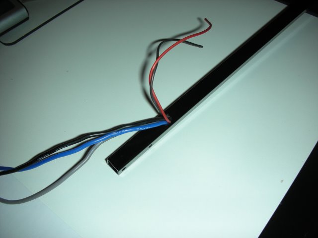
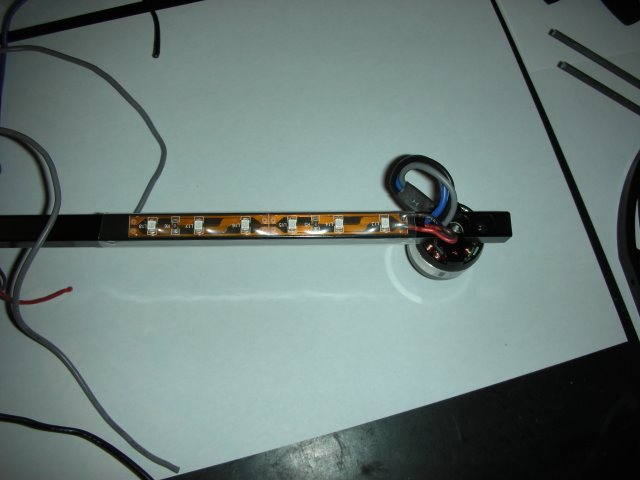
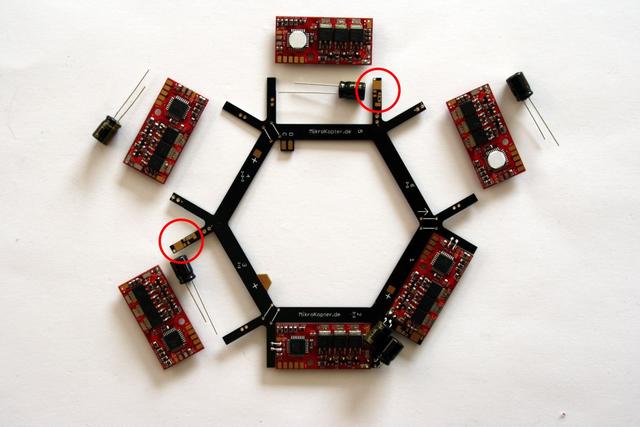
Then the brushless motors were mounted, and at the same time, I inserted the wires for the LED strips which will be mounted underneath the beams. One LED stripe will go on the red beam with red LEDs to see the drone's orientation in poor-sight circumstances. The other two LED stripes, green, were mounted at the back. At first sight, all these wires and so, seem to create a bit of chaos, but the developers have thought about that too, and created a kind of electrical distribution disk where all comes neatly together.
.
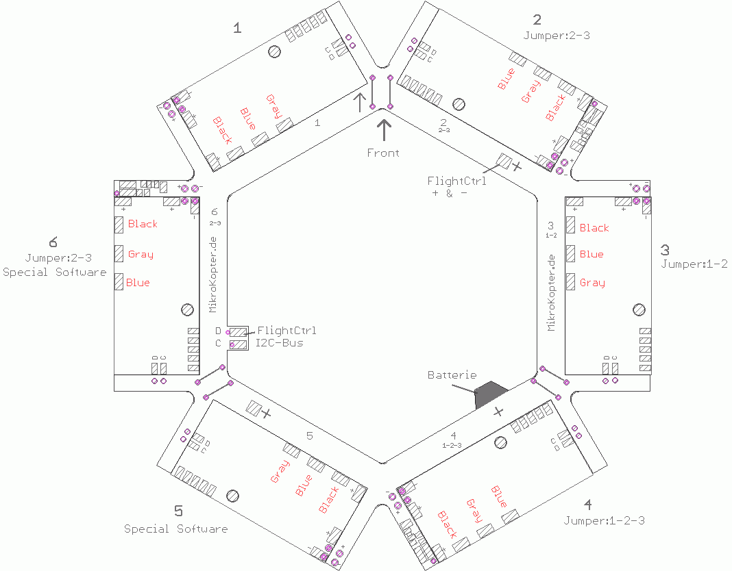
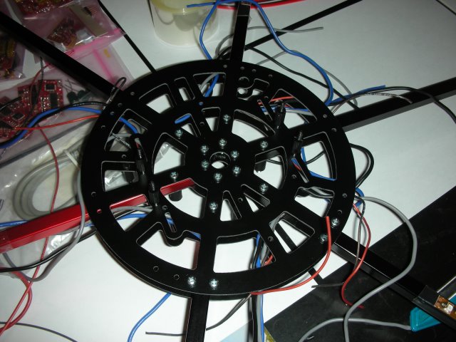
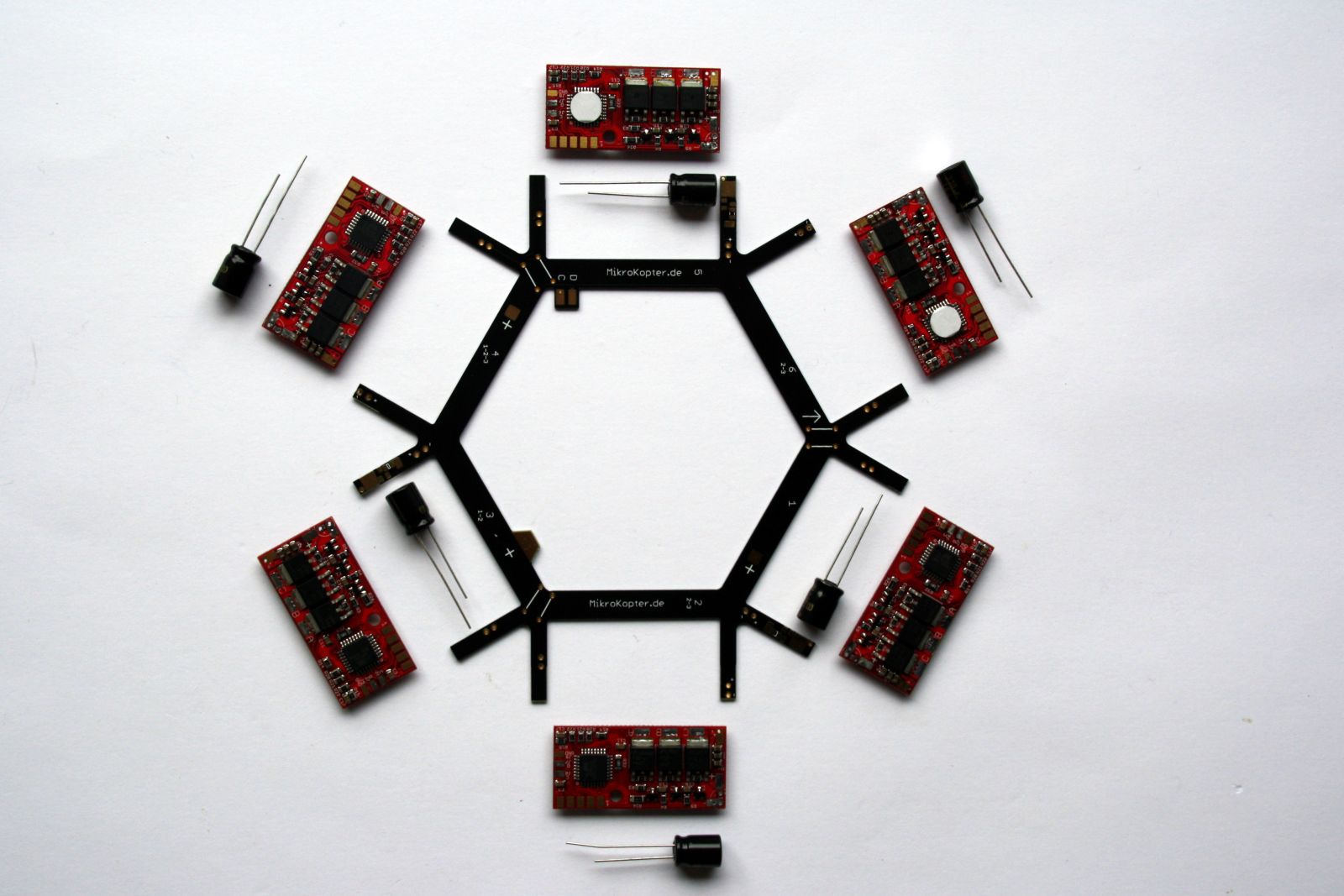
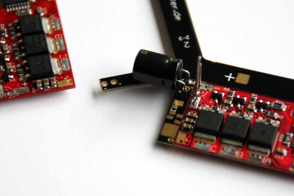
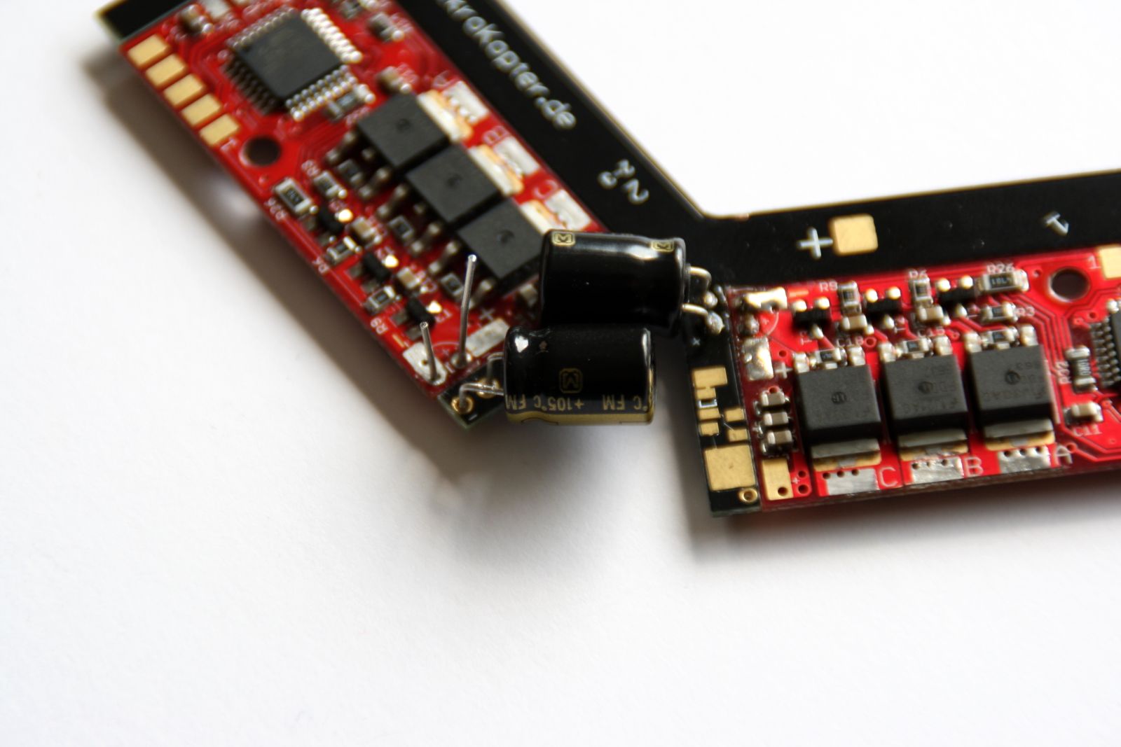
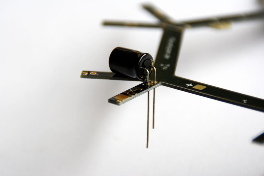
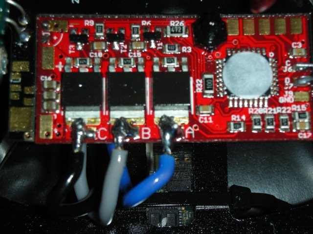
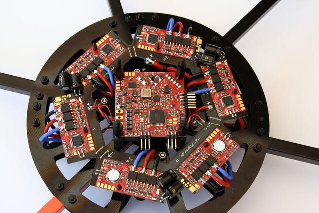
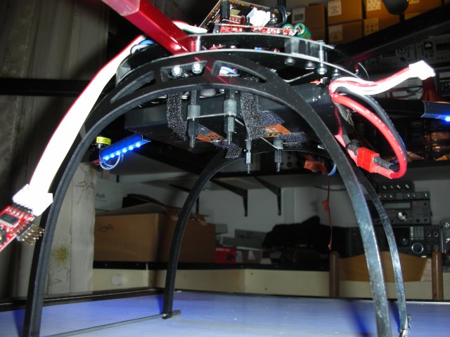
The distribution hexagon with the motor driver PCBs
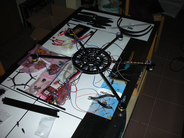
Now the beams. motors and the distribution hexagon are finished there is time to put together some electronics, such as the motor drivers, the GPS system, the flight controller, and the receiver part. It was a long and slow step-by-step process to prevent errors because a smokey startup would have been very expensive.
The distribution hexagon with the motor driver PCBs and capacitors to be installed
The distribution hexagon with the motor driver PCBs and capacitors to be installed
Then the motor driver PCBs were connected to the brushless motors, and the flight controller was soldered together, the hight-sensor was wrapped in rubber foam to prevent the airflow from the propellers from influencing the real air pressure at flying operation.
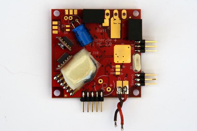
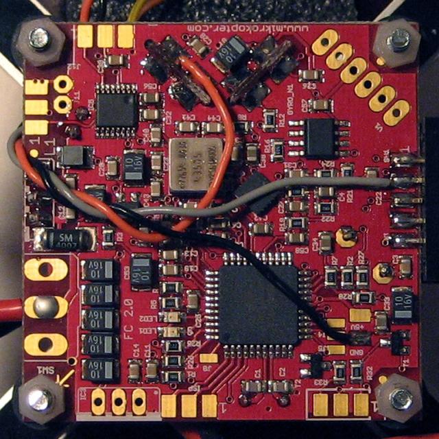
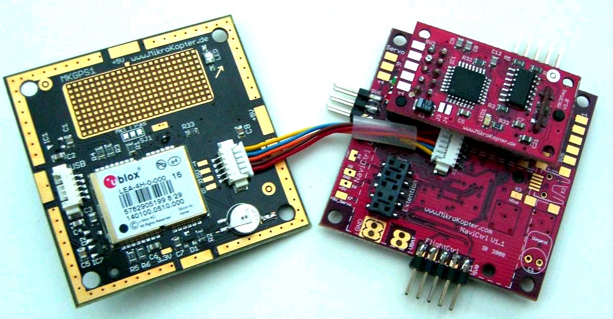
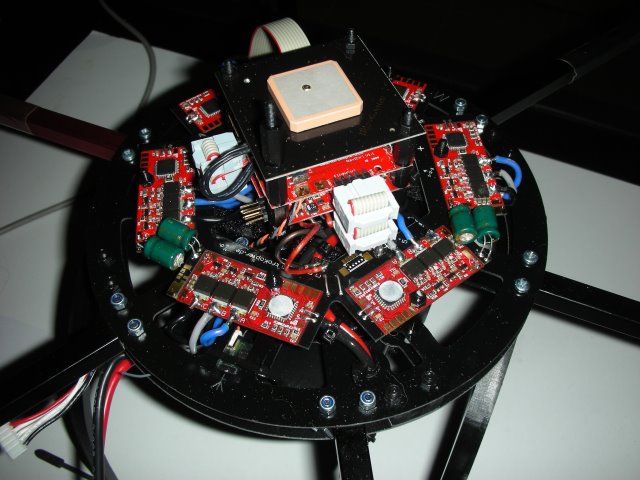
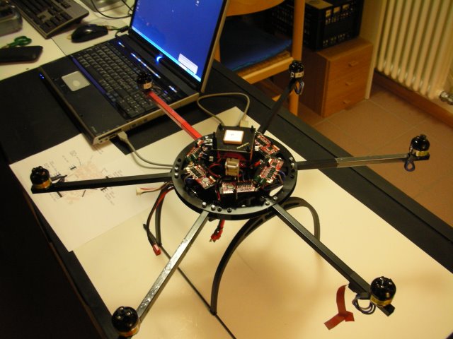
Now putting all the PCB boards together into a tower setup. At the top, the GPS receiver so that no obstructions are in the way to receive the satellite signals. This module consists of the antenna and the receiver on a separate PCB.
Then comes the flight controller, this module has a height sensor (pressure) to establish at what height the drone actually is flying. Before flight, this sensor should be calibrated at the start to prevent error readings, for example starting of a mountain region.
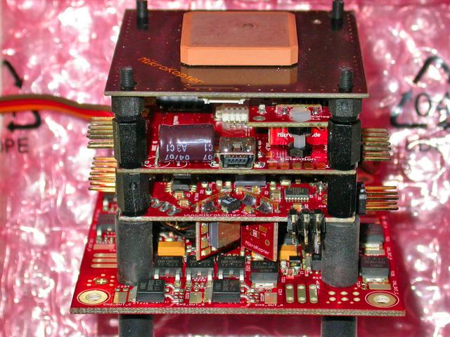
Then the assembled PCB tower can be put on the distribution hexagonal and connected with 10-pin flat cable to each other.
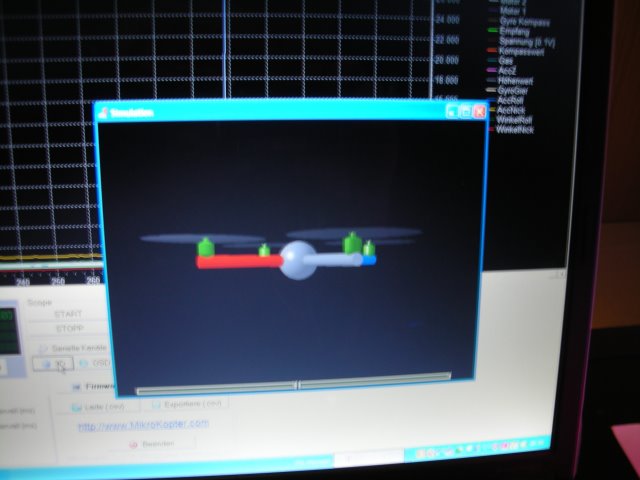
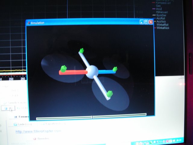
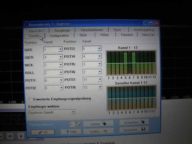
Now the whole assembly is mounted, I had to do some tests to be sure that all was connected correctly and the flight controller was working as it should. To do so, the Hexakopter package comes with some dedicated software that allows you to monitor all kinds of important parameters and signals coming from the various sensors on board.
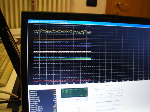
On the left, the Bluetooth module for data transmission, in the center connected to the drone flight controller, on the left, the first signals from the drone sensors. Magnetic compass, pressure, heading (X, Y, Z, acceleration sensors). what satellites are received to permit safe auto hovering, using the GPS signals to stabilize the height and X, Y position of the drone.
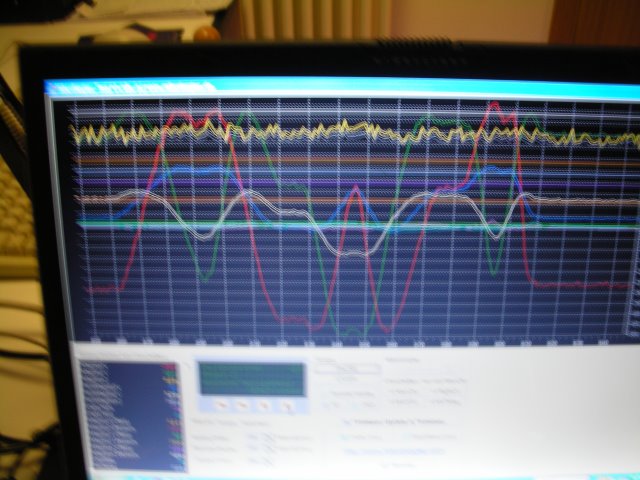
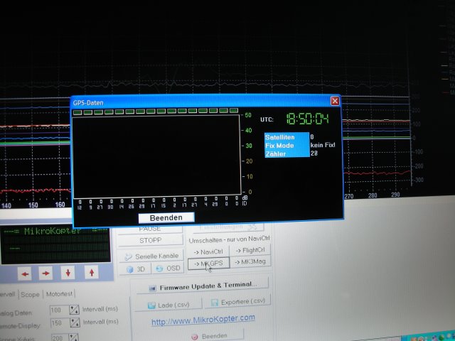
As the first test was performed inside the hobby basement, no satellite signals were available. Now I tested the acceleration sensors that will take care of the correct position during flight. Heading, tilt, rotate, and height.
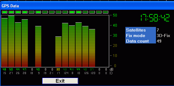
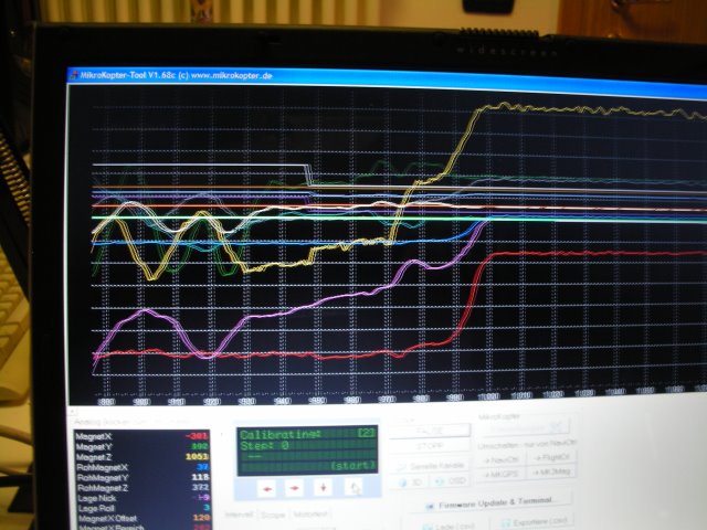
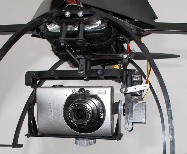
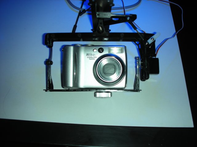
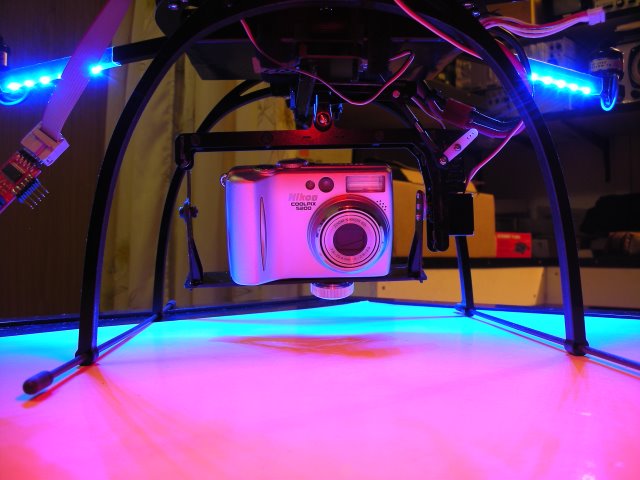
I went outside to test the GPS receiver and was really surprised by the good results of the system as you may see here above. Now the main structure was built, tested, and ready for the next step, I mounted the camera bracket that comes with the package. For a small camera as seen in the pictures, the bracket was performing enough but I wanted to put a better camera in the future so I made my own out of carbon-enforced resin, you will see it later on.
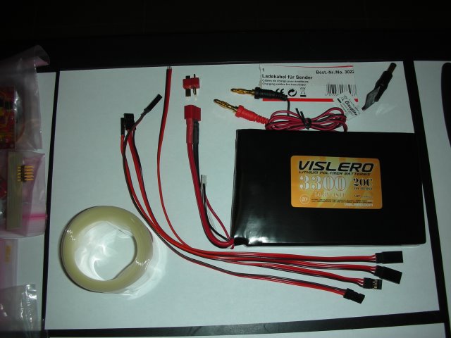
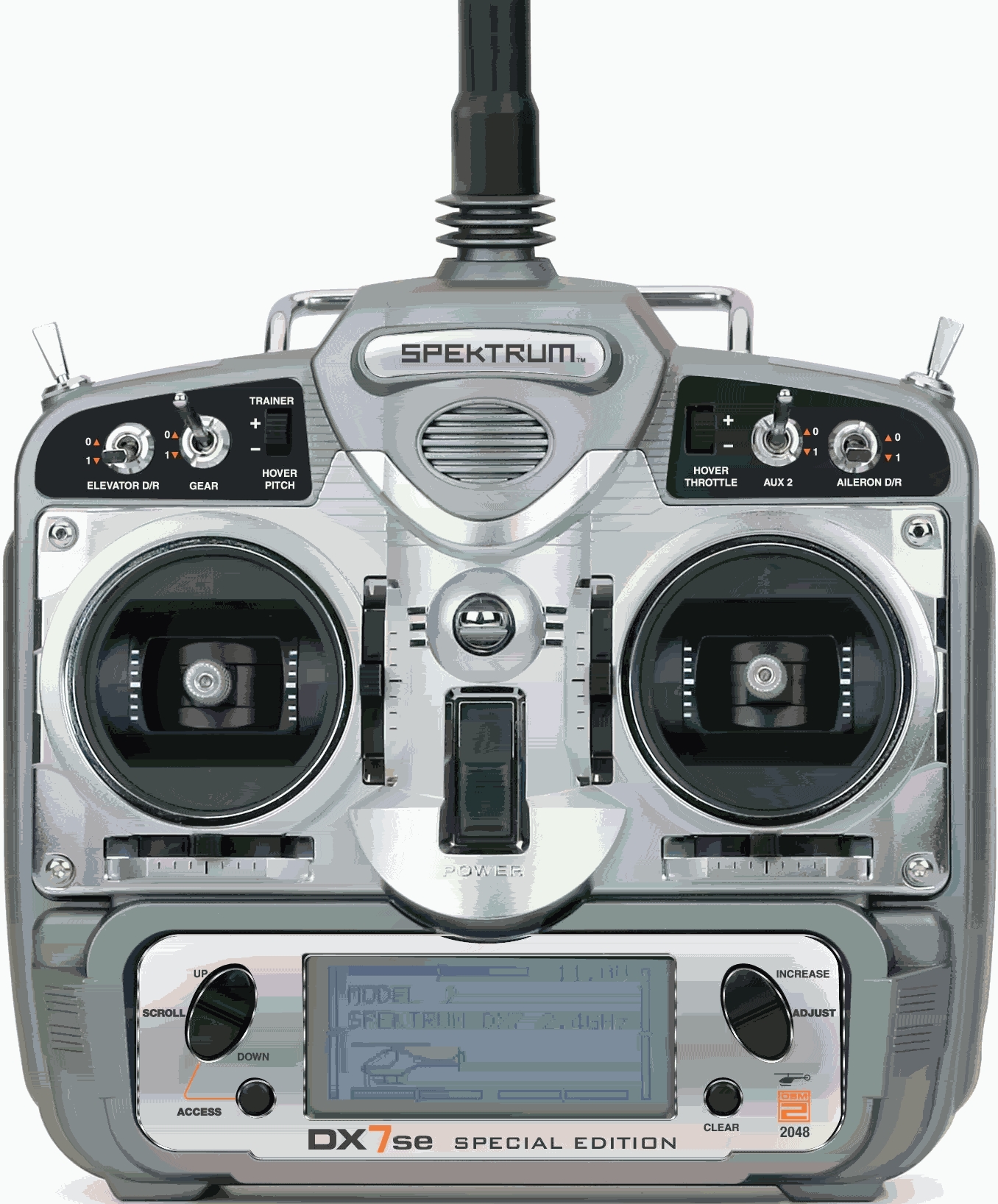
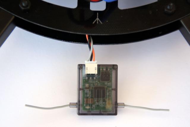
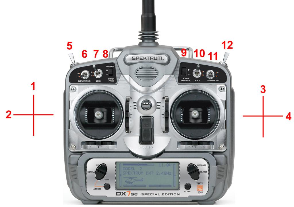
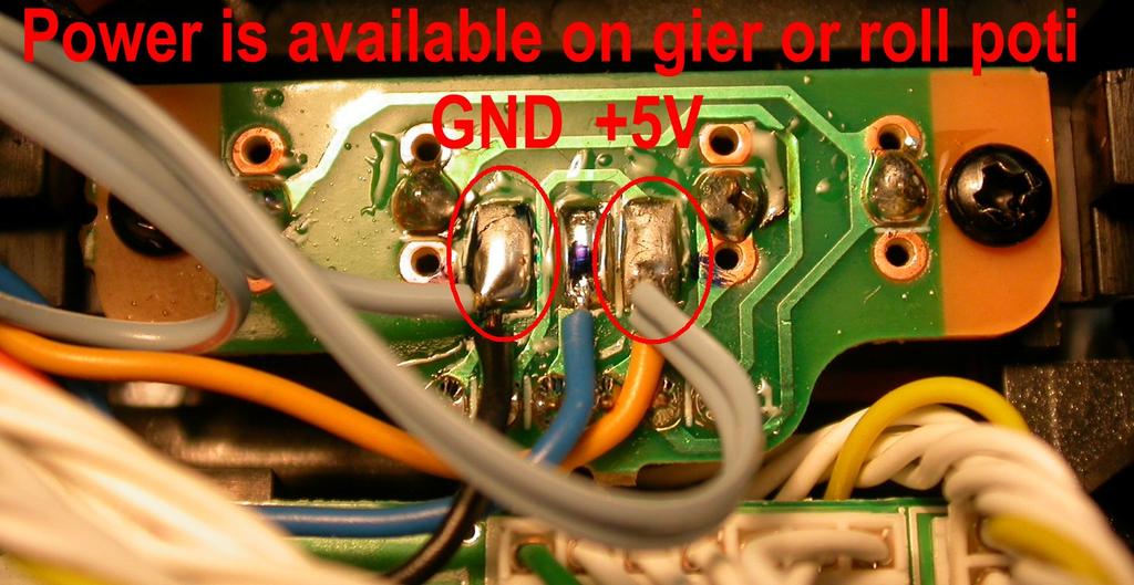
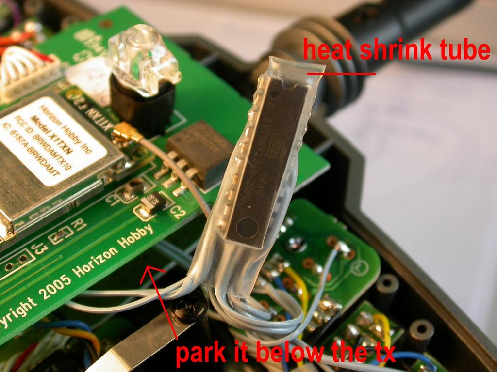
A drone cannot fly autonomously, so it needs a radio receiver and a remote control unit to do the job. I bought a Spektrum radio controller with 6 channels as it was the cheapest choice. This controller comes with a tiny 7-channel receiver as shown in the pictures below.
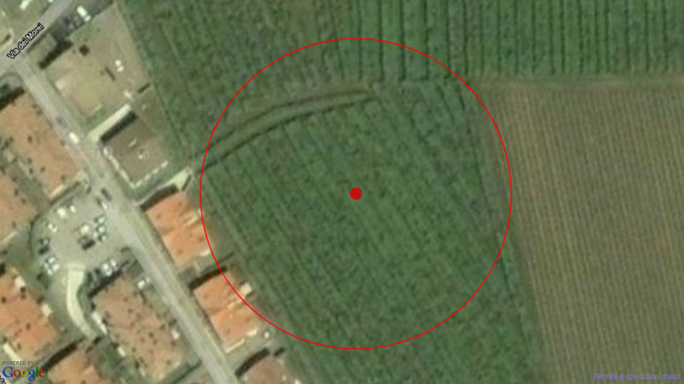
Now everything was ready to make a first flight attempt, I set up a Geo-Map to prevent the drone from getting out of this specific range, using the "Waypoint" option in the firmware. With this option, you can set several (geographic) points to fly to or from. Due to the "carefree" mode, you can set in the firmware, whatever the orientation the drone is, rotated or else, this option will control the drone just by pushing the joysticks right, left, ahead, or back. The drone will take care of interpreting the commends right so even a "newbie", as I was at the time could not cause drone loss or damage.
The new restrictions nowadays make the flying of this type of DIY drone's somewhat difficult. I hope you enjoyed your journey with this article. Unfortunately, the video's shot with this drone got lost in a computer crash. But you may have a look at the channel from the developers, there are still some video's left.