
While the FRG-8800 is an older model, the receiver still offers a lot of fun listening to the various frequencies. It has even a so-called CAT (Computer Aided Transceiver) connector to control the receiver through a Windows or DOS PC. Seen the age of the receiver, there are not many features to control but even with the few available, you can enter frequencies directly, move quickly up and down through frequencies, and control modes of the receiver. All of these features are available through the CAT interface that applies to the software operation of the FRG-8800. Unfortunately, Yaesu does not provide a means to control the Volume or Squelch using the CAT interface.
Knowing a little about Visual Basic(tm) programming it was really fun to write my own CAT Software. You will find a free copy (Beta Version) on the download page.
When I started the programming, first there was another problem to solve, because the receiver should be connected to the PC through a normally used serial port as RS232 type. The receiver's electronic circuits are based on TTL signals and those are NOT compatible with the RS232 standard so I had to make a converter first.
If you don’t want to make your own interface, you can use the "official" Yaesu FIF-232C Interface if you can find some (it converts 5V TTL to RS-232 polar) The easiest way to obtain an interface, USB or RS232 is eBay, the prices are different from EURO 15,- (RS232) to EURO 45,- (USB opto coupler)
On the market, you can buy very low-cost IC to make an easy home-made converter just look at the Interface page to see some samples.
Finished the interface I could finally start to do some programming. For the program I used Visual Studio and Visual Basic 6.0 - All graphics were home-made with Paint shop Pro 5.0 / 8.0
And finally, we have a Windows frequency logging and radio control program. This program has been tested with Windows Me and XP. You can scan frequency ranges, scan and select stored frequencies, and log your favorite frequencies by station. This program gives you virtually unlimited memory because the PC is used for memory storage. Just for trying (Beta Version), i have put a limit of 100 Memories.
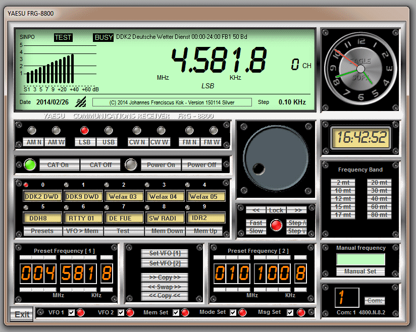
Some of the Features
- Turn the receiver on and off.
- Enter frequency directly to 10Hz in the range of 200kHz to 30MHz.
- Enter frequency directly in the range of 118MHz to 174MHz with an optional VHF Converter (FRV-8800) installed.
- Increase or decrease frequency using CH +/- in steps of 100Hz, 1kHz, etc. by clicking on the VFO Preset.
- There are two virtual VFOs that can be copied swapped and set alternately
- Select mode - AM, FM, LSB, USB, and CW.
- Select filter – Wide or Narrow in AM and CW mode.
- Connect to a computer RS-232C port with an optional Level Converter.
- Settable Parameters:
- The program now scans all available ports (1 to 16) and shows them in a dropdown menu where you can define Comports from 1 to 16
Virtual Status LEDs that show communications status, settable parameter entry, and some other parameter activated or not.
Naturally, the program will grow dynamically with the ideas and suggestions I hear from other users. Finally, it will be a program that will fit the FRG 8800 very well and have a lot of fun using it.
Just give it a try, It is free to use, but take care of the Interface because, without it, there can be some Smoke and Tears.
Remote Computer Control the CAT System
The CAT (Computer-Aided Transceiver) System was originally developed for external control of Amateur Transceivers by external personal computers. The simplified but powerful version of this system in the FRG-8800 offers vast potential for expanding the present functions of the receiver, and adding new functions as may be desired for specialized reception techniques that are not possible with the receiver alone.
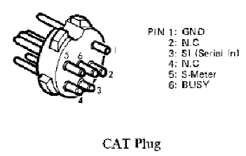
Physically, the CAT System is a serial data input port to the microprocessor in the FRG-8800, which accepts commands from an external computer via pin 3 of the CAT jack on the rear panel (pin 1 is ground).
This control data must be sent in groups of five bytes, "TTL" level <OV="MARK" and +5V="SPACE"), with eight data bits, two stop bits, and no parity, at 4800 bits/sec. Within the groups of five bytes, each byte must be sent within 300ms of the last. Since most computers are not equipped with an output port that provides this format, Yaesu offers the FIF-series CAT Interface Units, the appropriate one of which should be installed between the computer and the receiver.
The CAT jack on the FRG-8800 also provides a sample of the AGC (S-meter) voltage at pin 5, and of the squelch <BUSY=OV) status at pin 6. The AGC voltage can be converted into a digital pulse and used to inform the computer of the received signal level, either via the analog-to-digital converter in certain of the FIF-Units, or by an external A-to-D converter, either outboard or in the computer.
The squelch status can be passed to the computer via a TTL-level digital input port. While neither of these connections is necessary for external control, they do provide a means by which the operating condition of the receiver can be fed back to the computer, allowing interactive ("intelligent") control by the external computer.
External Control Programming
If anyone wants to write his own program, I have placed below some helpful information on how some of the commands should be implemented before sending them to the receiver.
There are just four types of commands used to control the FRG-8800:
-
External Control on/off. (CAT On/Off)
-
Frequency Set.
-
Power on/off.
-
Mode Set.
While this makes programming very simple, the tremendous flexibility that these offer when wisely applied in a creative program should be borne in mind. The CAT Command Chart shows the format of these commands. Note that the bytes are actually sent from left to right, chronologically on the serial data line, so that the Instruction byte is always sent last. For clarity, all bytes <8-bit values) are depicted in their hexadecimal (base 16) forms, with this indicated by an "H" appended to the two digits.
A) External Control On/Off
The Instruction byte (byte 5) for this command is zero, and it has two types: one is necessary to initialize external control at the start of a session (byte 4 - 0>, and the other to terminate external control at the end of a session <byte 4 = 80H, = 128 decimal). Bytes 1 - 3 may be any number (their value is irrelevant, but they must be sent). While external control is activated, the mode buttons, tuning controls, and keypad are all disabled, until the External Control Off command is sent, at which time the receiver will return to the last frequency and mode used, in the VFO mode. This command can be accepted by the FRG-8800 regardless of whether the receiver is switched on or off.
(B) Frequency Set
This command has an Instruction byte (5) of the value 1 and has just one function: to change the receiving frequency to that encoded in bytes 1 - 4 of the command. The encoded byte values appear "backward" from the frequency display, with the smallest frequency increments (least significant digits) in byte 1, sent first, and the largest increment (hundreds and tens of MHz digits) in byte 4.
While appearing awkward to humans, this format allows the microprocessor to handle the data efficiently.
Byte 1 has a special coding, in which the two hexadecimal digits (nibbles) of the byte are treated separately, in different ways. The left-hand digit is simply equivalent to the 100Hz digit (0 - 9) of the frequency.
However, the right-hand digit is a coded representation of the number of 25Hz steps to be appended to the frequency, with this digit equal to 1 for no 25Hz steps, 2 for one 25Hz step, and 4 for two 25!lz steps (50Hz), or 8 for three 25Hz steps {75Hz).
Note that these are the only acceptable values for the right-hand hex nibble: 1, 2, 4, or 8. So, for example, if byte 1 is 58H (hexadecimal), this represents 500 plus 75, or 575Hz.
Bytes 2, 3, and 4 are encoded more simply, with the total byte value (both digits) simply the hex number with the same two digits as the corresponding two decimal digits of the frequency. Byte 2 represents the ten's and one's decimal digits of the frequency, byte 3 the one's of MII2 and hundred's of kHz, and byte 4 the hundred's and ten's of MHz.
Note that the decimally converted hex value of each byte is not the same as the encoded value. For example, if byte 4 is 12H (hexadecimal), this represents a frequency of 120MHz, while the decimal conversion of 12H is actually 1 x 16 + 2 x 1, or 18 decimal. Make sure this point is clear before attempting to write a program.
Example:
To convert 14.25400 MHz into the proper byte code for sending to the receiver.
(1) Since the 100's and 25's of Hz are both zero, byte 1 is 01H (note that 00H is invalid for byte 1; since 1 in the right-hand digit is the correct code for zero Hz).
(2) The 10's and 1's of kHz digits are 5 and 4, respectively, so byte 2 is just 54H {which is actually 5 x 16 + 4, or 84 decimal: don't forget the encoding) .
(3) The 1's of MHz and 100's of kHz digits are 4 and 2, so byte 3 is 42H.
(4) The 100's of MHz is zero, and the 10's of MHz is 1 , so byte 4 is 01 H. If you are setting a frequency below 10 MHz, don't forget to make this byte zero.
Recall that since byte 1 is sent first, the command to send to set the FRG-8800 to 14.25400 MHz is, from left to right in the order of sending;
01H 54H 42H 01H 01H
Notice that the alphabetic digits of base 16 numbers, A through F, are never used in frequency commands. Also, since the values of bytes 1 through 3 are only relevant to the frequency set command, they can be left unchanged (as "dummy" values) when using other commands. This can be used to advantage in programming.
(C) Power On/Off Command
This command has two types, with a common Instruction byte (5) of 80H (128 decimal). The first type is sent when the receiver power is off, to turn it on. This ON command requires that byte 4 have the value FEH (254 decimal).
The second type is sent to switch the receiver off, and it requires that byte 4 have the value FFH (255 decimal). The values of bytes 1 - 3 don't matter, but again, they must still be sent. If the wrong command is sent {for example, if the OFF command is sent when the FRG-8800 is already off), nothing happens (so it's okay to do this).
(D) Mode Set Command
This command has eight types, one for each mode. Byte 5 is always 80H (128 decimal), just like the Power on/off commands, so be careful. Byte 4 must be 00H for AM wide, 08H (8 decimals) for AM narrow, 01H (1 decimal) for LSB, 02H (2 decimal) for USB, 03H (3 decimals) for CW wide, 0BH (11 decimals) for CW narrow, 04H (4 decimal) for FM wide, or 0CH (12 decimal) for FM narrow. Of course, if you send 04H for FM-wide without the optional FM-wide Unit installed, nothing happens. Again, the value of bytes 1-3 doesn’t matter, but they must still be sent.
CAT SYSTEM COMMAND CHART
|
Command byte n°
|
Byte Data |
Function
|
||||
|
Parameter field *Inst |
||||||
|
1 |
2 |
3 |
4 |
5 |
||
|
CAT ON CAT OFF |
X** |
X |
X |
0H |
0H |
Activate CAT |
|
X |
X |
X |
80H |
0H |
Deactivate CAT |
|
|
Power ON Power OFF |
X |
X |
X |
FEH |
80H |
Receiver ON |
|
X |
X |
X |
FFH |
80H |
Receiver Off |
|
|
Frequency Set |
nnH |
nnH |
nnH |
nnH |
01H |
See *** below |
|
AM-W AM –N LSB USB CW-W CW-N FM-W FM-N |
X |
X |
X |
0H |
80H |
AM Wide mode |
|
X |
X |
X |
8H |
80H |
AM Narrow mode |
|
|
X |
X |
X |
1H |
80H |
Lower side band |
|
|
X |
X |
X |
2H |
80H |
Upper side band |
|
|
X |
X |
X |
3H |
80H |
CW Wide mode |
|
|
X |
X |
X |
BH |
80H |
CW Narrow mode |
|
|
X |
X |
X |
4H |
80H |
FM Wide mode |
|
|
X |
X |
X |
CH |
80H |
FM Narrow mode |
|
* Instruction Byte - sent last, determines nature of command
** "X" signifies “dummy" byte: value unimportant, but must be sent to fill command to 5-byte format.
*** "nnH" values are hexadecimal codes for frequency data, explained in the text.
RS 232 Basics
In the early 1960s, a standards committee, today known as the Electronic Industries Association, developed a common interface standard for data communications equipment. At that time, data communications was thought to mean digital data exchange between a centrally located mainframe computer and a remote computer terminal, or possibly between two terminals without a computer involved. These devices were linked by telephone voice lines and consequently required a modem at each end for signal translation. While simple in concept, the many opportunities for data error that occur when transmitting data through an analog channel require a relatively complex design. It was thought that a standard was needed first to ensure reliable communication, and second to enable the interconnection of equipment produced by different manufacturers, thereby fostering the benefits of mass production and competition. From these ideas, the RS232 standard was born. It specified signal voltages, signal timing, signal function, a protocol for information exchange, and mechanical connectors.
Physically, the CAT System is a serial data input port to the microprocessor in the FRG-8800, which accepts commands from an external computer via pin 3 of the CAT jack on the rear panel (pin 1 is ground).

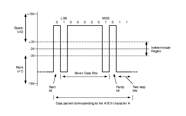
This control data must be sent in groups of five bytes, "TTL" level 0V = "MARK" and +5V = "SPACE", with eight data bits, two stop bits, and no parity, at 4800 bits/sec. Within the groups of five bytes, each byte must be sent within 300ms of the last. Since most computers are not equipped with an output port that provides this format, we have to think about something that resolves our problem.
The electrical specification of the serial port is contained in the EIA (Electronics Industry Association) RS232C standard. It states many parameters such as:
A "Space" (logic 0) will be between +3 and +25 Volts.
A "Mark" (Logic 1) will be between -3 and -25 Volts.
The region between +3 and -3 volts is undefined.
An open circuit voltage should never exceed 25 volts. (In Reference to GND)
A short circuit current should not exceed 500mA.
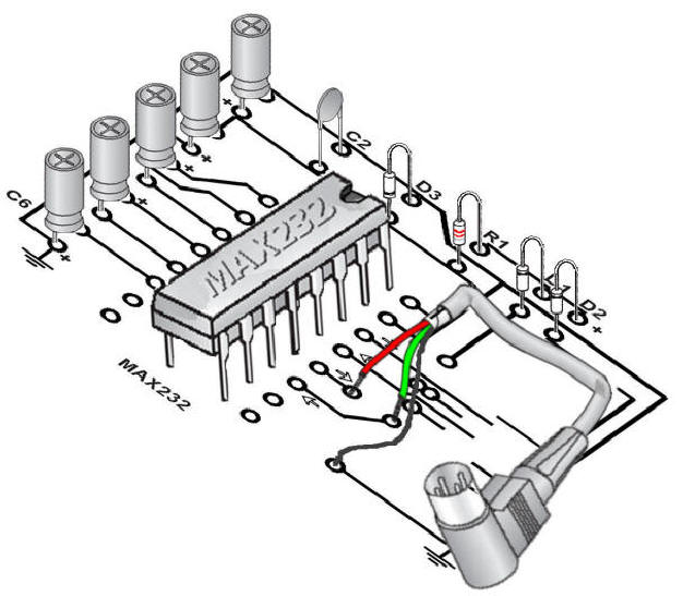
It is obvious that we need some converter to deal with the different voltages. Fortunately, we can find in almost all the electronic shops the famous MAX232 chip, a bunch of transistors and other electronic stuff, “melted” into e piece of plastic with some pins around it also called IC. Almost all digital devices that we may use require either TTL or CMOS logic levels. Therefore the first step to connecting a device to the RS-232 port is to transform the RS-232 levels back into 0 and 5 Volts. As we have already discovered, this is done by RS-232 Level Converters. As a device, we will use the MAX-232. It includes a Charge Pump, which generates +10V and -10V from a single 5v supply. This I.C. also includes two receivers and two transmitters in the same package. This is handy in many cases when you only want to use the Transmit and Receive data Lines. You don't need to use two chips, one for the receive line and one for the transmit line. However all this convenience comes at a price, but compared with the price of designing a new power supply it is very cheap. Below you will find the MAX232 pin layout and block diagram.
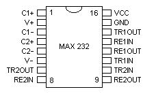
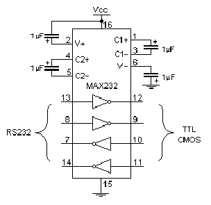
In spite of the MAX 232 basic circuit reported with his Datasheet, I changed the electrolytic capacitor values from 10µF to 1µF

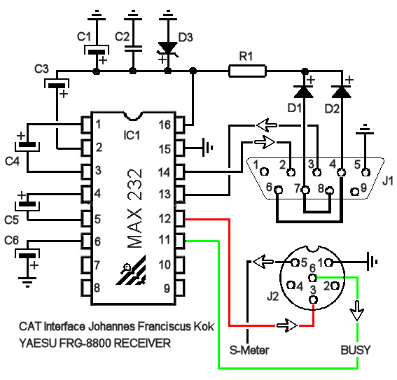
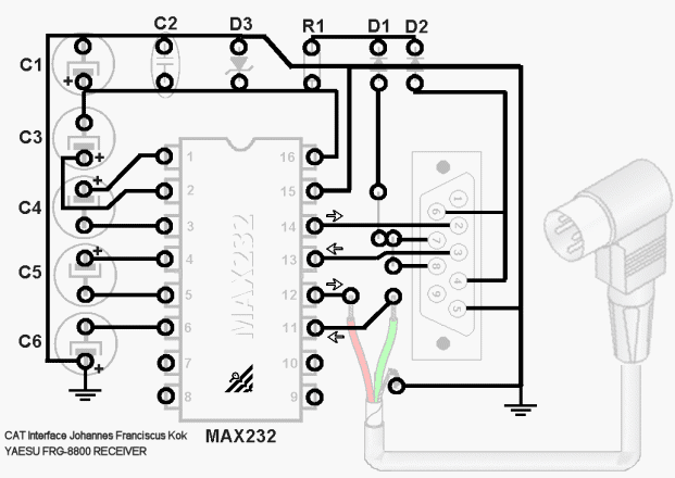
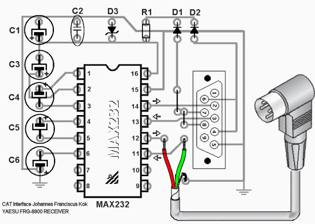
As a device, we will use the MAX-232. It includes a Charge Pump, which generates +10V and -10V from a single 5v supply. But now first the shopping list for the electronic store:
-
IC1 DIL16, MAX232
-
SC1 Socket DIL16
-
C1 Electrolytic capacitor 4.5mm, 10µF 63V
-
C2 Ceramic 0.1µF
-
C3 Electrolytic capacitor 4.5mm, 1µF 63V
-
C4 Electrolytic capacitor 4.5mm, 1µF 63V
-
C5 Electrolytic capacitor 4.5mm, 1µF 63V
-
C6 Electrolytic capacitor 4.5mm, 1µF 63V
-
D1 SI-diode, 1N4148
-
D2 SI-diode, 1N4148
-
D3 Zener diode 4.7V
-
R1 Resistor 220R
-
J1 Dsub 15 pole female (on PCB or as Plug with cable)
-
J2 CAT (DIN Audio plug) connector

ATTENTION: USE OF THIS SOFTWARE IS SUBJECT TO THE SOFTWARE PRODUCT "AS IS" WARRANTY STATEMENT BY DOWNLOADING AND INSTALLING THE SOFTWARE, YOU ARE AGREEING TO BE BOUND BY THESE TERMS. IF YOU DO NOT AGREE TO ALL OF THESE TERMS, DO NOT DOWNLOAD AND INSTALL THE SOFTWARE ON YOUR SYSTEM.

************************* Download your free CAT Software package here now *************************
*************** Disclaimer ***************
JOHANNES FRANCISCUS KOK (FRANCO) SOFTWARE PRODUCT "AS IS" WARRANTY STATEMENT
DISCLAIMER. TO THE EXTENT ALLOWED BY LOCAL LAW, THIS SOFTWARE PRODUCT ("SOFTWARE") IS PROVIDED TO YOU "AS IS" WITHOUT WARRANTIES OR CONDITIONS OF ANY KIND, WHETHER ORAL OR WRITTEN, EXPRESS OR IMPLIED. FRANCO SPECIFICALLY DISCLAIMS ANY IMPLIED WARRANTIES OR CONDITIONS OF MERCHANTABILITY, SATISFACTORY QUALITY, NON-INFRINGEMENT, AND FITNESS FOR A PARTICULAR PURPOSE.
LIMITATION OF LIABILITY. EXCEPT TO THE EXTENT PROHIBITED BY LOCAL LAW, IN NO EVENT WILL FRANCO OR ITS SUBSIDIARIES, AFFILIATES, OR SUPPLIERS BE LIABLE FOR DIRECT, SPECIAL, INCIDENTAL, CONSEQUENTIAL, OR OTHER DAMAGES (INCLUDING LOST PROFIT, LOST DATA, OR DOWNTIME COSTS), ARISING OUT OF THE USE, INABILITY TO USE, OR THE RESULTS OF USE OF THE SOFTWARE, WHETHER BASED IN WARRANTY, CONTRACT, TORT OR OTHER LEGAL THEORY, AND WHETHER OR NOT ADVISED OF THE POSSIBILITY OF SUCH DAMAGES.
Your use of the Software is entirely at your own risk. Should the Software prove defective, you assume the entire cost of all service, repair or correction.
NOTE. EXCEPT TO THE EXTENT ALLOWED BY LOCAL LAW, THESE WARRANTY TERMS DO NOT EXCLUDE, RESTRICT OR MODIFY, AND ARE IN ADDITION TO, THE MANDATORY STATUTORY RIGHTS APPLICABLE TO THE LICENSE OF THE SOFTWARE TO YOU.
![]()
In the package are included some LCD Fonts, just install them into the Windows Font directory to obtain a real "Digital" look on the program display.
Download is for registered users only
Download the full package as ZIP here:
FRG-8800.ZIP


